Download
1 / 27
570 likes | 1.7k Views
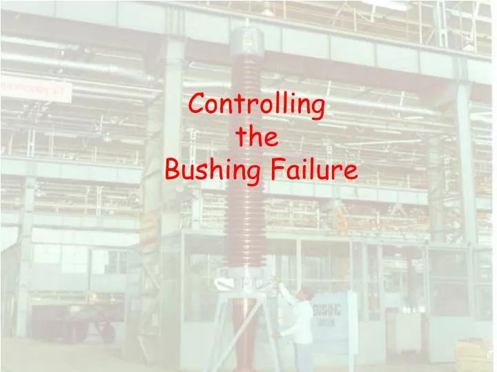
Controlling the Bushing Failure. 800 kV OIP Condenser Bushing. Bushing. Bushing is defined as a structure carrying one or several conductors through a partition such as a wall or tank etc. and insulating it or them there from

E N D
800 kV OIP Condenser Bushing
Bushing • Bushing is defined as a structure carrying one or several conductors through a partition such as a wall or tank etc. and insulating it or them there from • It is a link between transformer winding and overhead transmission line. • Insulation used is paper, oil and porcelain • It is hermetically sealed to avoid exposure of oil • Bushing has to bear all the abnormalities of Power System & Environment as well.
General Construction • The active part of Bushing consists of an Oil Impregnated Paper (OIP) core. This is manufactured from superior grade Kraft paper wound on metal tube with metallic foils interposed at pre-determined diameters. • The condenser core is assembled with mounting flange, porcelain insulators and top cap. • The assembled bushing is vacuum dried and impregnated with high grade degassed and dehydrated transformer oil.
MAJOR PARTS OF BUSHING Top Cap Top Porcelain Flange Bottom Porcelain
Types of Failure • Mechanical damage • Thermal Breakdown • Electrical Failure
Mechanical Damage • Damage to porcelain • Shifting of porcelain w.r.t. flange • Crushing of gaskets or sealing rings • Crack or breakage of flange
Factors affecting performance of Bushing • Atmospheric condition like pollution, humidity, and ambient temperature. • Temperature rise of joints. • Partial Discharge • Thermal instability • Loss of oil • Altitude
Causes of Electrical failure in Bushings • Insulation failure • Ingress of moisture • Leakage of oil • Internal discharges • Disconnection of earthing link of test tap • Failure due to high voltage such as lightning, switching etc.
Condition Monitoring at Site • Physical Observation • Crack in porcelain • Damage to sheds • Contamination • Oil level • Surface discharges • Storage of Bushing
Condition Monitoring at Site • Tan Delta & Capacitance measurement Tan Delta is the dielectric loss angle. Limiting Value for OIP Bushing = 0.007(Max.) For measuring tan delta at site Schering Bridge is required. • New Bushing yet to be installed • Bushing already in service
Significance of Tan Delta & Capacitance Measurement • It reveals increased dielectric losses (I2R) in the insulation • The presence of moisture in the insulation is indicated by Tan delta • Voids in Oil Impregnated Paper insulation which may give rise to internal corona • Short circuited condenser foils are indicated by the increased Capacitance
Factors affecting Tan Delta Measurement • Ambient conditions • Temperature of transformer oil around the lower end of bushing • Pollution level at site • Induction effect of the neighboring lines
Guidelines for measurement of Tan Delta at site • Position of bushing should be vertical • If mounted on transformer, remove top terminal connections • Clean the porcelain with a non-fluffy cloth • Check for oil level and any leakage • Short the bushings of other phases which are not under test • Avoid measurement on a rainy season or when humidity is more than 70%
Bushings What do we measure? • Tan δ – same as winding insulation • Capacitance – same as winding insulation • Dielectric loss – same as winding insulation • C1 – main insulation • C2 – tap insulation
High-Voltage Cable • Test Includes • Main C1 Core Insulation Test Mode: UST Low Voltage Lead Guard Ground Lead Bushing and Apparatus Ground Bushings How do we measure?
Low Voltage Lead • Test Includes • Tap Insulator • Core Insulation between tapped Layer and Bushing Ground Sleeve • Portion of Liquid or Compound Filler High Voltage Lead Test Mode: GST-Guard IC2 Guard I & W Meter Bushings How do we measure?
Bushings What does it reveal ? • Moisture; • Carbonisation of insulation; • Short circuited condenser layers; • Contamination of oil by dissolved materials or conducting particles; and • Open circuits such as break in the band between the ground and mounting flange.
Analysis of Results 1)High Tan delta (between0.007 and 0.01) Ingress of moisture in bushing insulation 2)Very High Tan delta (Beyond 0.01) High humidity, Strong ageing of insulation 3) Low Tan delta Weak Potential connection 4) High Capacitance This indicates Partial Breakdown.
Analysis of Results Variation in Capacitance • With in 5% - Bushing Acceptable • With in 5% to 10% - Monitor Bushing closely • More than 10% - Inform the manufacturer or Replace Bushing
Condition Monitoring at Site • Monitoring of hot spots with thermo-vision camera Abnormally high temperature indicates any of the following • Improper engagement of top terminal with pull through connector • Looseness of terminal connector • Loose connection between bushing lead and winding lead
Equipotential condensers