Download
1 / 26
260 likes | 266 Views
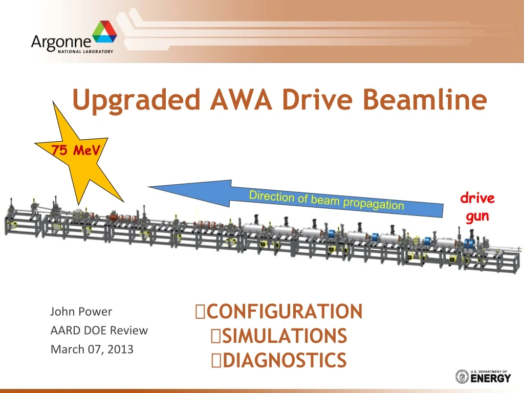
Upgraded AWA Drive Beamline CONFIGURATION SIMULATIONS DIAGNOSTICS. 75 MeV. John Power AARD DOE Review March 07, 2013. drive gun. Direction of beam propagation. The AWA Upgrade drive beamline. 75 MeV. Direction of beam propagation. drive gun. Upgrade Goals.

E N D
Upgraded AWA Drive BeamlineCONFIGURATIONSIMULATIONSDIAGNOSTICS 75 MeV John Power AARD DOE Review March 07, 2013 drive gun Direction of beam propagation
The AWA Upgrade drive beamline 75 MeV Direction of beam propagation drive gun Upgrade Goals Original Drive Beam (Achievements) Upgraded Drive Beam (Targets) • Single bunch operation • 75 MeV • Q = 0.1-100 nC • @ 100 nC • sz = 2 mm • High Current: ~16 kA • emittance < 200 um • Bunch train operation • 10 bunches x 100 nC • 32 bunches x 30 nC • Train Length = 10 - 50 ns • Single bunch operation • 15 MeV • Q = 0.1-100 nC (world record!) • @ 100 nC • sz = 3 mm • High Current: ~11 kA • emittance < 200 um • Bunch train operation • 4 bunches x 20 nC • 16 bunches x 5 nC • Train Length = 10 - 25 ns
Outline • Beamline configuration and installation of the beamline components • Beam Dynamics Simulations • Beam Commissioning Plan
Building up the beamline … 1. beamline configuration AND INSTALLATION
Installation of beamline components (PROGRESS) ONGOING COMPLETED RF Gun *Conditioned to Full power (Spring ‘11) Waveguides *installed Winter 2013 Solenoids *arrived Summer 2012 *installed Winter 2013 DIAGNOSTIC BEAMLINE 6 New RF cavities *tuned & balanced Fall ‘12 *installed Winter ’13 +Spectrometer +Quads +Def Cavity +etc.
1300 MHz rf cavity from design … …to installed in beamline RF window waveguide Installed RF cavity 1for Pin = 10 MW and Qb = 100 nC, sz = 2 mm. RF conditioning next
Expected beam performance 2. beamline simulation
f f f f f + RF power distribution Total Power Budget = 96 MW DG 75 MeV DL6 DL5 DL4 DL3 DL2 DL1 11 MW 11 MW 11 MW 11 MW 13 MW 14 MW 14 MW K4 K2 K3 25MW K1 PWR 30MW 25MW 28 MW Klystron Maximum Operated Power Power (90%) K1 (Orig.) 28 MW 25 MW K2 (Litton) 30 MW 27 MW K3 (Thales) 25 MW 22 MW K4 (Thales) 25 MW 22 MW Total 110 MW 96 MW 6 MW 5 MW 10 MeV WL1 WG
Start-to-end simulations (Parmela/Impact-T) Simulations performed Single bunch Bunch train (beam loading and its mitigation) Combined effects GUN DL4 DL2 DL5 DL6 DL1 DL3 Full Width (3s) Beam Envelope (mm) z= 1093 cm Example: 100 nC beam through the linac
1. Single bunch start-to-end simulations Beam parameters: Q = 100 nC, R (at cathode) = 8.0 mm, z = 3.40 ps • Single Bunch Wakefields*: • negligible effect on transverse phase-space • increased correlated energy spread. • decreased longitudinal emittance. *Impact-T implementation of the wakefields based on, K. L. F. Bane, SLAC-PUB-9663, 2003 and benchmarked to ABCI.
2. Bunch Train start-to-end simulations initial stored energy BUNCH TRAIN U0 U0- DU Ub=N*DU U0-N*DU • Goal: minimize droop Ub/U0 @ Qb=1mC • Solution: • large stored energy (U0) rf cavity design • vary launch phase during operation
2. Bunch Train start-to-end simulations Multibunch wakefield effects and its mitigation T • 10 bunches on crest • Bunches at different phases T+Dt
3. Bunch Train start-to-end simulations On crest (DE/E = 26%) Vary phase (DE/E = 2.3%) Vary phase (DE/E = 1.3%) 5 bunches x 100 nC
Example: 40 nC x 10 bunch train quad triplet Solenoid Solenoid GUN DL4 DL2 DL5 DL6 DL1 DL3 DLA L=0.5 m radius = 2.5 mm
Diagnostics 3. beamline commissioning
Drive Beam Commissioning Front-end diagnostics Challenges for Diagnostics sx,y sx,y Q Q Drive beamline front-end (19 MeV ) <x>, <y> <x>, <y> sx,y Q Main Diagnostic Beamline sx,y sx,y sx,y Transverse: sigX/Y, emittanceY Longitudinal: E, DE/E, sigZ 75 MeV Drive Beamline • wide dynamic range • charge: (100 pC < Q < 100 nC) • emittance: (1 mm < eN < 200 mm) • fast pulse trains • pulse train: single microbunch to bunch trains of up to 32 bunches spaced by 769 ps.
Front-end diagnostics Installed Winter 2012-13 • In-flange FCT-ICT from Bergoz • FCT: rise time ~175ps resolve bunches inside the bunch train • ICT: calibrated measurement of total charge in train Normal incidence YAG screen 50mm x 100 mm 45o incidence YAG screen 50mm x 100 mm Diagnostic Cross #2 <x>, <y> • Diagnostic Cross #1 • Faraday cup • YAG • mirror 66mm RF cavity Gun Laser Input Solenoid Trim Drive beamline front-end (19 MeV )
Imaging Station:(inside vacuum) installed Winter 2013 (ongoing) Resolution target Normal incidence YAG screen 50mm x 100 mm YAG:Ce Screen • reduced depth of focus (normal incidence ) • High resolution (100 mm thickness) Dual YAG-alignment screen camera • 45o Si-wafer, double-side mirror • 300 mm: very little energy deposited, • very flat: good for laser alignment • can be used for OTR at other locations (if YAG screen is removed)
Imaging Station (outside vacuum)To be Installed Spring ‘13 To be installed Spring 2013 Remote: Zoom, Focus, and Iris 10X Motorized Zoom Focal Length = 12.0 - 120.0 (mm) Motorized Lens Controller Zoom, Focus, and Iris • The cameras are mounted: • below table • inside of the legs 8-to-1 DB25 Switch
Main Diagnostic Beamline To be installed Spring 2013 TEST AREA 75 MeV Longitudinal: Dp, p [MeV] A A A 0.762m 1m 0.762m End of linac DIAGX8 dump DIAGX7 1.0 m 1.0 m 0.4 m 1.5 m 1m A 15 deg Cav 6 dump DIAGX2 DIAGX3 2m 1m Def Cav DIAGX5 DIAGX4 DIAGX1 DIAGX6 Longitudinal: sz [mm] Q[nC] Transverse: ey,rms,normalized [mm] Transverse: sx,y[mm] USAF target YAG+ mirror DIAGNOSTIC CROSS Slit Trim OTR Quad BPM ICT A
Transverse: ey,normalized [mm] NORMAL INCIDENT YAG:Ce USAF TARGET TUNGSTEN SLIT OTR SCREEN 1m dump TRIM COIL 1m A 15 deg A A A A dump 2m 1m • Transverse: Emittance measurement • Multiple slits: 50um, 100um, 300um • Centered slit: quick estimate • Motorized slit: accurate measurement • Multiple drifts: ~70cm, ~1.7m, ~2.7m 0.5mm tungsten q=64 mrad
Longitudinal: sz [mm] 0.762m 1m dump 1m A 15 deg A A A dump 2m 1m Longitudinal: sz [mm] • Longitudinal: Bunch length • RF Deflecting Cavity • OTR mirror + Streak camera
Longitudinal: sz [mm] OFF • Deflecting cavity first results • 3.4 MV @ 4.2 MW (1300 MHz) • bunch length measurements • longitudinal phase space • Resolution study ON Lb La Vperp Q=0.1 nC & E=14 MeV 200 cm 1/Vperp Lb Lb Resolution ~ 35 fs @ 0.1 nC 1 ps @ 100 nC @14 MeV
Longitudinal: {E, DE/E} DIAGX4 dump Spectrometer based on existing 15o dipole DIAGT4 DIAGQ1 BEND DIAGT2 DIAGT3 DIAGX2 A A dump DIAGX3 (100 mm) SCREEN (50 mm) QUAD BEND SCREEN LSOL BEND QUAD BEND LSOL DRIFT 24
Transverse: centroid {BPM system} • Stripline BPM (recently commissioned front end) • lock beam phase to LLRF (new effort at AWA) • slow orbit feedback system (new effort at AWA) ~400ps 1.3 GHz BP filter (commercial) BPPM circuit board (Euclid-ANL; in house) 1.3 GHz Stripline BPM (in house)
Summary • Beam dynamics simulations for the 75 MeV beamline - Complete • Front-end (<19 MeV) beamline – Spring 2013 • Install beamline (1st cavity and diagnostics) - Complete • Condition 1st RF cavity to full power • Generate and characterize single bunches and trains • 75 MeV beamline – Spring/Summer 2013 • Install remainder of beamline (cavities and diagnostics) - Complete • Layout of 75 MeV diagnostic beamline - Complete • Condition RF cavities 2-6 • Install diagnostic beamline • Begin full beam commissioning at 75 MeV • First wakefield experiments – Fall 2013