Download
1 / 30
300 likes | 320 Views
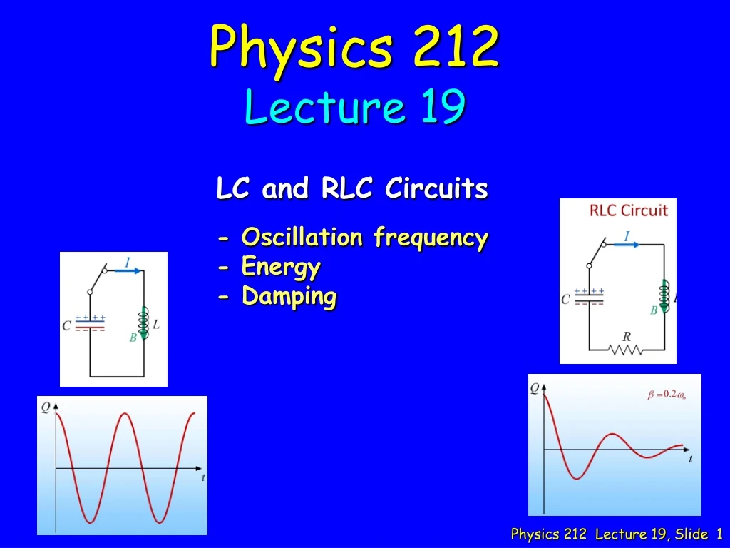
Physics 212 Lecture 19. LC and RLC Circuits. - Oscillation frequency - Energy - Damping. Music. Who is the Artist? Stephane Grappelli Pearl Django Mark O’Connor’s Hot Swing Trio Miles Davis Cassandra Wilson. Physics 212 Lecture 3. Some Exam Stuff. Exam Thu. night (Mar. 29) at 7:00

E N D
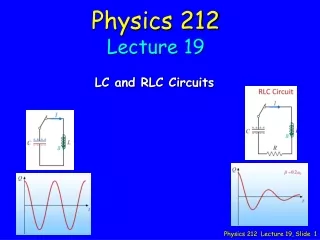
Physics 212 Lecture 19 LC and RLC Circuits - Oscillation frequency - Energy - Damping
Music • Who is the Artist? • Stephane Grappelli • Pearl Django • Mark O’Connor’s Hot Swing Trio • Miles Davis • Cassandra Wilson Physics 212 Lecture 3
Some Exam Stuff • Exam Thu. night (Mar. 29) at 7:00 • Covers material in Lectures 9 – 18 • Bring your ID: Rooms determined by discussion section (see link) • Conflict exam at 5:15 • Final Exam • “Regular”: Fri. May 4, 1:30; “Conflict”: Fri. May 11, 8:00 • Sign up for the conflict in the gradebook if you wish
Your Comments “I am really confused with this stuff. The PreLecture tries to tell us too much too fast. I have lost my intuition! :(” “The concepts today were quite intuitive. Unfortunately, there were a lot of very scary looking equations on the slides that are not on our formula sheet. Are we expected to memorize these equations and/or perform calculations with them?” The LC solutions are easy to derive starting from what you know, NOT RLC “Waves (graphs) and how the signs of charge swap.” “There are so many different combinations of circuit components now, and I’m starting to find it increasing difficult to keep straight how each circuit behaves. Please go over the check points as well; I got stuck on a few of them!!! ” WILL DO ! “Okay I get it. But one thing...does omega equal d/dt? That’s not a term though...it’s just notation...I don’t get that. Also, why don’t we just use superconducting LC circuits to supply electricity???” “If this comment makes it onto the board today, no more puppies will be killed by horrible puns.”
- + + - Circuit Equation: where LC Circuit I C Q L
C L Checkpoint 1a At time t = 0 the capacitor is fully charged with Qmax and the current through the circuit is 0. What is the potential difference across the inductor at t = 0 ?A) VL = 0 B) VL = Qmax/C C) VL = Qmax/2C “The current going through the inductor is going to be 0 so by ohm’s law there is no voltage difference over the inductor.” “no current, simple potential equation Q=cv ” “V = (1/2) (Q/C)”
C L since VL = VC Checkpoint 1a At time t = 0 the capacitor is fully charged with Qmax and the current through the circuit is 0. What is the potential difference across the inductor at t = 0 ?A) VL = 0 B) VL = Qmax/C C) VL = Qmax/2C The voltage across the capacitor is Qmax/C Kirchhoff's Voltage Rule implies that must also be equal to the voltage across the inductor
L C m F = -kx k a x Same thing if we notice that and Pendulum…
L C Time Dependence I + + - -
Checkpoint 1b C L At time t = 0 the capacitor is fully charged with Qmax and the current through the circuit is 0. What is the potential difference across the inductor when the current is maximum ?A) VL = 0 B) VL = Qmax/C C) VL = Qmax/2C “The change in current becomes 0 when the current is maximum.” “This is the maximum voltage across that capacitor.” “Since the voltage is dependent on the amount of charge that is left in the capacitor it is Q/2C”
Checkpoint 1b C L At time t = 0 the capacitor is fully charged with Qmax and the current through the circuit is 0. What is the potential difference across the inductor when the current is maximum ?A) VL = 0 B) VL = Qmax/C C) VL = Qmax/2C dI/dt is zero when current is maximum
Checkpoint 1c C L At time t = 0 the capacitor is fully charged with Qmax and the current through the circuit is 0. How much energy is stored in the capacitor when the current is a maximum ?A) U = Qmax2/(2C) B) U = Qmax2/(4C) C) U = 0 “All the energy is in the capacitor” “current is maximum when energy is evenly divided between the capacitor and inductor” “All the energy would be stored in the inductor when the current is maximum.”
Checkpoint 1c C L At time t = 0 the capacitor is fully charged with Qmax and the current through the circuit is 0. How much energy is stored in the capacitor when the current is a maximum ?A) U = Qmax2/(2C) B) U = Qmax2/(4C) C) U = 0 Total Energy is constant ! ULmax = ½ LImax2 UCmax = Qmax2/2C I = max when Q = 0
C L Checkpoint 2a The capacitor is charged such that the top plate has a charge +Q0 and the bottom plate -Q0. At time t=0, the switch is closed and the circuit oscillates with frequencyw= 500 radians/s. L = 4 x 10⁻³ H w = 500 rad/s + + - - What is the value of the capacitor C?A) C = 1 x 10⁻³ F B) C = 2 x 10⁻³ F C) C = 4 x 10⁻³ F “w = 1 / sqrt(LC)” “use q=vc formula” “All the charge is built up in the capacitor and so it is 4x10^-3”
C L Checkpoint 2a The capacitor is charged such that the top plate has a charge +Q0 and the bottom plate -Q0. At time t=0, the switch is closed and the circuit oscillates with frequencyw= 500 radians/s. L = 4 x 10⁻³ H w = 500 rad/s + + - - What is the value of the capacitor C?A) C = 1 x 10⁻³ F B) C = 2 x 10⁻³ F C) C = 4 x 10⁻³ F
C L +Q0 -Q0 Checkpoint 2b closed at t=0 Which plot best represents the energy in the inductor as a function of time starting just after the switch is closed? “Since the current is initially 0, the energy begins at zero and oscillates, allowing the energy to be negative.” “oscillates between positive and negative, does not start at zero” “It starts at 0 and cannot be negative.”
C L +Q0 -Q0 Energy proportional to I2 U cannot be negative Current is changing UL is not constant Initialcurrent is zero Checkpoint 2b closed at t=0 Which plot best represents the energy in the inductor as a function of time starting just after the switch is closed?
closed at t=0 +Q0 -Q0 C L Checkpoint 2c When the energy stored in the capacitor reaches its maximum again for the first time after t=0, how much charge is stored on the top plate of the capacitor? • A) +Q0 • B) +Q0 /2 • C) 0 • -Q0/2 • -Q0 “V is the same as before, so Q is the same” “only 1/2 the charge is needed” “Current direction swaps around so the signs on the capacitor plates changes as well.”
closed at t=0 +Q0 -Q0 C L Q is maximum when current goes to zero Checkpoint 2c When the energy stored in the capacitor reaches its maximum again for the first time after t=0, how much charge is stored on the top plate of the capacitor? • A) +Q0 • B) +Q0 /2 • C) 0 • -Q0/2 • -Q0 Current goes to zero twice during one cycle
…the physics under the hood is still very simple !! Physics Truth #N: Even though the answer sometimes looks complicated…
Add R: Damping Just like LC circuit but energy and the oscillations get smaller because of R …but answer looks kind of complicated Concept makes sense…
The elements of a circuit are very simple: This is all we need to know to solve for anything !
Repeat… A Different Approach Start with some initialV, I, Q, VL Now take a tiny time stepdt (1 ms)
Calculation V C L R The switch in the circuit shown has been closed for a long time. At t = 0, the switch is opened. What is QMAX, the maximum charge on the capacitor? • Conceptual Analysis • Once switch is opened, we have an LC circuit • Current will oscillate with natural frequency w0 • Strategic Analysis • Determine initial current • Determine oscillation frequency w0 • Find maximum charge on capacitor
Calculation BEFORE switch is opened: all current goes through inductor in direction shown The switch in the circuit shown has been closed for a long time. At t = 0, the switch is opened. IL V C L R What is IL, the current in the inductor, immediately AFTER the switch is opened? Take positive direction as shown. • IL < 0 (B) IL = 0 (C) IL > 0 Current through inductor immediately AFTER switch is opened IS THE SAME AS the current through inductor immediately BEFORE switch is opened
Calculation VC=0 AFTER switch is opened: BEFORE switch is opened: dIL/dt ~ 0 VL = 0 VC cannot change abruptly UC = ½ CVC2 = 0 !! VC = 0 VC = 0 IL The switch in the circuit shown has been closed for a long time. At t = 0, the switch is opened. V C L R IL(t=0+) > 0 The energy stored in the capacitor immediately after the switch is opened is zero. • TRUE (B) FALSE BUT: VL = VC since they are in parallel IMPORTANT: NOTE DIFFERENT CONSTRAINTS AFTER SWITCH OPENED CURRENT through INDUCTOR cannot change abruptly VOLTAGE across CAPACITOR cannot change abruptly
Calculation IL The switch in the circuit shown has been closed for a long time. At t = 0, the switch is opened. V C L R VC(t=0+) = 0 IL(t=0+) > 0 What is the direction of the current immediately after the switch is opened? • clockwise (B) counterclockwise Current through inductor immediately AFTER switch is opened IS THE SAME AS the current through inductor immediately BEFORE switch is opened BEFORE switch is opened: Current moves down through L AFTER switch is opened: Current continues to move down through L
Calculation IL IL V BEFORE switch is opened: VL=0 C L V = ILR IL R The switch in the circuit shown has been closed for a long time. At t = 0, the switch is opened. V C L R VC(t=0+) = 0 IL(t=0+) > 0 What is the magnitude of the current right after the switch is opened? • (B) (C) (D) Current through inductor immediately AFTER switch is opened IS THE SAME AS the current through inductor immediately BEFORE switch is opened VL = 0
Calculation V C L R Imax Qmax C L C L When Q is max (and I is 0) When I is max (and Q is 0) The switch in the circuit shown has been closed for a long time. At t = 0, the switch is opened. IL Hint: Energy is conserved VC(t=0+) = 0 IL(t=0+) =V/R What is Qmax, the maximum charge on the capacitor during the oscillations? • (B) (C) (D)
Follow-Up 1 V C L R Vmax can be greater than V IF: OR The switch in the circuit shown has been closed for a long time. At t = 0, the switch is opened. Is it possible for the maximum voltage on the capacitor to be greater than V? IL Imax =V/R • YES (B) NO We can rewrite this condition in terms of the resonant frequency: We will see these forms again when we study AC circuits!!