Download
1 / 62
630 likes | 826 Views
Chapter 4: A Simple Computer. We explore the organization of a computer which is the structure and function of the components in the computer Structure : how the components in the computer are connected together, how they communicate Function : what they do

E N D
Chapter 4: A Simple Computer • We explore the organization of a computer which is • the structure and function of the components in the computer • Structure: how the components in the computer are connected together, how they communicate • Function: what they do • Specifically, we will explore the • CPU • Memory • I/O • Bus • A primitive instruction set (MARIE) • MARIE is the book’s simple computer • We will examine it to understand what an instruction set is, before we being our examination of the instruction set for Intel
The CPU • The central processing unit (or processor) • Is the brain of the computer • It does all the processing • What does this mean? • The CPU is in charge of executing the current program • Each program is stored in memory along with data • The CPU is in charge of retrieving the next instruction from memory (fetch), decoding and executing it • Execution usually requires the use of ALU and temporary storage in registers • Some instructions cause data movement (memory accesses, input, output) and some instructions change what the next instruction is (branches) • We divide the CPU into two areas • Datapath – registers and ALU (the execution unit) • Control unit – circuits in charge of performing the fetch-execute cycle
User registers These store data and addresses These are manipulated by your program instructions Example: Add R1, R2, R3 R1 R2 + R3 Computers will have between One and hundreds of registers Possibly divided into data and address registers Registers are usually the size of the computer’s word size 32 or 64 bits today, previously it had been 8 or 16 bits Control registers Registers that store information used by the control unit to perform the fetch-execute cycle PC – the memory location of the next instruction IR –the current instruction being executed Status flags – information about the results of the last instruction executed (was there an overflow, was the result positive, zero or negative?) Two Kinds of Registers
Consists of circuits to perform arithmetic and logic operations Adder Multiplier Shifter Comparator Operations in the ALU set status flags (carry, overflow, positive, zero, negative) Also, possibly, temporary registers before moving results back to register or memory ALU
in charge of managing the fetch-execute cycle It sends out control signals to all other devices A control signal indicates that the device should activate or perform it’s function For instance: Instruction fetching requires sending the PC value to main memory signaling memory to read when the datum comes back from memory, move it to the IR increment the PC to point to the next instruction These operations are controlled by the control unit Now the control unit decodes the instruction signals the proper ALU circuit(s) to execute it Control Unit
In order to regulate when the CU issues its control signals, computers use a system clock At each clock pulse, the control unit goes on to the next task Register values are loaded or stored at the beginning of a clock pulse ALU circuits activate at the beginning of a clock pulse The System Clock
Clock performance is based on the number of pulses per second, or its Gigahertz rating This is a misleading spec The number of clock pulses (cycles) that it takes to execute one instruction differs from one computer to the next Assume computer A takes 10 clock cycles per instruction but has a 1 Gigahertz clock speed Assume computer B can execute 10 instructions in 11 cycles using a pipeline, but has a 250 Megahertz clock speed Which one is faster? B even though its clock is slower! The System Clock
Comparing Clocks • It is difficult to computer CPU performance just by comparing clock speed • You must also consider how many clock cycles it takes to execute 1 instruction • How fast memory is • How fast the bus is • In addition, there are different clocks in the computer, the Control Unit and the whole CPU are governed by the system clock • There is usually a bus clock as well to regulate the usage of the slower buses
A bus is a collection of wires that allow current to flow over them The current is the information being passed between components There are 3 parts to a bus data bus for data and program instructions control bus control signals from the CU to the devices, and feedback lines for ack that they are ready or for interrupting the CPU address bus the address of the memory location or I/O device that is to perform the given operation The Bus
Additionally, computers may have multiple buses Local bus connects registers, ALU and CU together System bus connects CPU to main memory Expansion or I/O bus connects System bus to I/O devices The Bus
More on Buses • Buses connect two types of devices • Masters • Devices that can initiate requests • CPU • some I/O devices • Slaves • Devices that only respond to requests from masters • Memory • some I/O devices
More on Buses Point-to-point Buses • Some buses are dedicated • The bus directly connects two devices (point-to-point bus) • Most buses connect multiple components • multipoint Multipoint network Multipoint Expansion bus
Main memory connects to this bus through pins The I/O subsystem connects to this bus through the expansion bus The bus carries three types of information The address from the CPU of the intended item to be accessed The control information (read versus write, or status information like “are you available?”) The data, either being sent to the device, or from the device to CPU The System Bus
expansion bus • The expansion bus • is the collection of expansion slots and what gets plugged into them • Here we see interface cards (or expansion cards), each with the logic to interface between the CPU and the I/O device (e.g., printer, MODEM, disk drive)
Who gets to use the bus? • In a point-to-point buses this is not a problem • In the expansion bus where multiple I/O devices may want to communicate between themselves and the CPU or memory at the same time – we need a form of Bus Arbitration • Daisy chain arbitration • Each device has a bus request line on the control bus • When a device wants to use the bus, it places its request and the highest priority device is selected (this is an unfair approach) • Centralized parallel arbitration • The bus itself contains an arbiter (a processor) that decides • The arbiter might become a bottleneck, and this is also slightly more expensive • Distributed arbitration • Devices themselves to determine who gets to use the bus, usually based on a priority scheme, possibly unfair • Distributed arbitration using collision detection • It’s a free-for-all, but if a device detects that another device is using the bus, this device waits a short amount of time before trying again
I/O Subsystem • There are many different types of I/O devices, collectively known as the I/O Subsystem • Since I/O devices can vary in their speed and usage, the CPU does not directly control these devices • Instead, I/Omodules, orinterfaces, take the CPU commands and pass them on to their I/O devices
How to communicate with the right I/O device? • To communicate to the right I/O device, the CPU addresses the device through one of two forms • Memory-mapped I/O • Isolated I/O
Memory-mapped I/O • the interface has its own memory which are addressed as if they were part of main memory, so that some memory locations are not used, they are instead registers in the I/O interfaces • So each of these is given its own address • these addresses overlap those of memory so that a request issued to one of these memory addresses is actually a request of I/O, not memory and memory ignores the request. In such a system, the addresses are the earliest (say the first 5000 addresses).
Isolated I/O • In isolated I/O, the 5000 or so addresses are separate from memory, so that we need an extra control line to indicate if the address is a memory address or an I/O address. In memory-mapped I/O, the early addresses are shared so that, if one of these addresses is sent out, memory ignores it
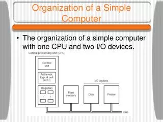
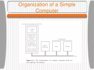
Memory Organization Memory is organized into byte or word-sized blocks • Each block has a unique address • This can be envisioned as an array of cells • The CPU accesses memory by sending an address of the intended access and a control command to read or write • The memory module then responds to the request appropriately • A decoderis used to decode the binary address into a specific memory location
Dividing Memory Across Chips • Main memory usually consists of more than one RAM chip • Each memory chip can store a certain amount of information • However, architects decide how memory is spread across these chips • For instance, do we want to have an entire byte on a single chip, or spread a byte across 2 or more chips? • Here, a word (16 bits) is stored in two chips in the same row
Interleaving Memory • Main memory usually consists of more than one RAM chip • Hence if you buy memory to upgrade you buy a Memory Module • Access is more efficient when memory is organized into banks of chips with the addresses interleaved across the chips • in high-order interleaving, the high order address bits specify the memory bank/module • Using high-order interleave • The advantage of high-order interleave is that two different devices, working on two different areas of memory, can perform their memory accesses simultaneously • e.g., one device accesses address 5 and another accesses 31 • low-order interleave • the low order bits of the address specify which memory bank contains the address of interest • Consecutive memory locations are on consecutive chips • The advantage of lower-order interleave is that several consecutive memory accesses can be performed simultaneously • For instance, fetching 4 consecutive instructions at one time
Interrupts • CPU performs the fetch-execute cycle on your program repeatedly without pause, until the program terminates • What happens if an I/O device needs attention? • What happens if your program tries to do an illegal operation? • What happens if you want to run 2 or more programs in a multitasking mode? • You cannot do this without interrupts • An interrupt • Is the interruption of the CPU so that it can switch its attention from your program to something else (an I/O device, the operating system)
The Interrupt Process • At the end of each fetch-execute cycle, the CPU checks to see if an interrupt has arisen • Devices send interrupts to the CPU over the control bus • If the instruction causes an interrupt, the Interrupt Flag (in the status flags) is set • If an interrupt has arisen, the interrupt is handled as follows • The CPU saves what it was doing (PC and other important registers are saved to the run-time stack in memory) • The CPU figures out who raised the interrupt and executes an interrupt handler to handle that type of interrupt • interrupt handler is a set of code, stored in memory • Once the interrupt has been handled, the CPU restores the interrupted program by retrieving the values from the run-time stack
A Simple Computer • We now put all of these elements together into a reduced computer (MARIE) • Machine Architecture that is Really Intuitive &Easy • MARIE is too easy, it is not very realistic, so we will go beyond MARIE as well • We will explore MARIE’s • CPU (registers, ALU, structure) • Instruction set (the instructions, their format – how you specify the instruction, addressing modes used, data types available • Interrupts, I/O • Some simple programs in MARIE
Data stored in binary, two’s complement Stored programs stores program data and instructions in same memory 16-bit word size with word addressing (you can only get words from memory, not bytes) 4K of main memory using 12 bit addresses, 16-bit data MARIE’s Architecture
16-bit instructions (4 bits for the op code, 12 bits for the address of the datum in memory) MARIE’s Architecture
Registers: AC this is the only data register (16 bits) PC (12 bits) IR (16 bits) Status flags MAR – stores the address to be sent to memory, 12 bits MBR stores the datum to be sent to memory or retrieved from memory, 16 bits 8-bit input and 8-bit output registers MARIE’s Architecture
MARIE CPU • The structure of our CPU with the registers shown • MAR sends to memory, the MBR stores the data being sent to memory or retrieved from memory • InREG and OutREG receive data from and send data to I/O respectively
MARIE’s interconnection • The registers are interconnected, and connected with main memory through a common data bus. • Each device on the bus is identified by a unique number that is set on the control lines whenever that device is required to carry out an operation. • Separate connections are also provided between the accumulator and the memory buffer register, and the ALU and the accumulator and memory buffer register. • This permits data transfer between these devices without use of the main data bus.
MARIE’s Fetch-Execute Cycle • PC stores the location in memory of the next Instruction • 1) fetch instruction by sending the address to memory (PC to MAR to memory) • 2) memory sends back instruction over data bus, to MBR, move it to IR, increment PC • 3) Decode the instruction (look at op code, place 8-bit data address in MAR if needed • If operand (Memory value) required, fetch it from memory • operand is the part of a computer instruction which specifies what data is to be manipulated or operated on. A computer instruction describes an operation such as add or multiply X, while the operand specify on which X to operate as well as the value of X • 5) Execute instruction • 6) If necessary, process interrupt
MARIE’s ISA • A computer’s instruction set architecture specifies the format of its instructions and the primitive operations that the machine can perform. • The ISA is an interface between a computer’s hardware and its software. • Some ISAs include hundreds of different instructions for processing data and controlling program execution. • The MARIE ISA consists of only 13 instructions.
MARIE’s Instructions • This is the format of a MARIE instruction: • The fundamental MARIE instructions are:
MARIE has a major flaw in that all data must be stored in memory and the Memory addresses known at compile time • What about using pointers? • We have to add instructions that have indirect access to memory to allow for pointers, so we add AddI and JumpI • We also add Clearto clear the accumulator • We also add JnSto permit procedure calls (jump but also save the PC so we can return when done with the procedure)
MARIE’s Instructions • This is a bit pattern for a LOAD instruction as it would appear in the IR • We see that the • opcode is 1 • address from which to load the data is 3
MARIE’s micro-operations • Each of our instructions actually consists of a sequence of smaller instructions called microoperations. • The exact sequence of microoperations that are carried out by an instruction can be specified using register transfer language (RTL). • In the MARIE RTL, we use the notation • M[X] to indicate the actual data value stored in memory • Location X • to indicate the transfer of bytes to a register or memory location.
Example of microoperations • The RTL for the LOAD instruction is • The RTL for the ADD instruction is MAR X MBR M[MAR], AC MBR Cycle 1 Cycle 2 MAR X MBR M[MAR] AC AC + MBR Cycle 1 Cycle 2 Cycle 3
Example: Add 2 Numbers This code will add the two numbers stored at memory location 104 and 105 Load 104 loads the AC with the value at 104 (0023) Add 105 adds to the AC the value at 105 (FFE9) Store 106 takes the value in the AC (000C) and moves it to location 106 Halt then stops the program
4.6 Extending Our Instruction Set • So far, all of the MARIE instructions that we have discussed use a direct addressing mode. • This means that the address of the operand is explicitly stated in the instruction. • It is often useful to employ a indirect addressing, where the address of the address of the operand is given in the instruction. • If you have ever used pointers in a program, you are already familiar with indirect addressing.
ADDI X instruction • Add indirect specifies the address of the address of the operand • Use the value at location X as the actual address of the data operand to add to AC • The following RTL tells us what is happening at the register level MAR X MBR M[MAR] MAR MBR MBR M[MAR] AC AC + MBR Example AC = 0020 ADDI 500 Result AC = 1021
JnS X • Another helpful programming tool is the use of subroutines. • The jump-and-store instruction, JNS, gives us limited subroutine functionality. • Store the PC at address X, and jump to address X+1 • The details of the JNS instruction are given by the following RTL MBR PC MAR X M[MAR] MBR MBR X AC 1 AC AC + MBR PC AC Does JNS permit recursive calls? النداءات التكرارية
SKIPCOND • Skips the next instruction according to the value of the AC • The RTL for the this instruction is the most complex in our instruction set If IR[11 - 10] = 00 then If AC < 0 then PC PC + 1 else If IR[11 - 10] = 01 then If AC =0 then PC PC + 1 else If IR[11 - 10] = 10 then If AC > 0 then PC PC + 1
Bit pattern for SKIPCOND instruction • This is a bit pattern for a SKIPCOND instruction as it would appear in the IR • We see that the opcode is 8 and bits 11 and 10 are 10, meaning that the next instruction will be skipped if the value in the AC is greater than zero.
Assemblers and Assembly Language • Compare the machine code to the assembly code • You will find the assembly code much easier to decipher • Mnemonics instead of op codes • Variable names instead of memory locations • Labels (for branches) instead of memory locations • Assemblyis an intermediate language between theinstruction set (machine language) and the high-level language • The assembler is a program that takes an assembly language program and assembles it into machine language, much like the compiler compiles a high-level language program
Discussion on Assemblers • Mnemonic instructions, such as LOAD 104, are easy for humans to write and understand. • They are impossible for computers to understand. • Assemblers translate instructions that are comprehensible to humans into the machine language that is comprehensible to computers • In assembly language, there is a one-to-one correspondence between a mnemonic instruction and its machine code • With compilers, this is not usually the case. • A= B+C • A=add(B,C) • A=B + C
Discussion on Assemblers • Assemblers create an object program file from mnemonic source code in two passes • First pass • the assembler assembles as much of the program is it can, while it builds a symbol tablethat contains memory references for all symbols in the program. • Second pass • the instructions are completed using the values from the symbol table.
Example program • Note that we have included • twodirectivesHEX and DEC that specify the radix of the constants. • First pass, we have • a symbol table • partial instructions. • Second pass • the assembly is complete. • (35)10= 0023h • (-23)10= FFE9
4.6 Extending Our Instruction Set 100 | LOAD Addr 101 | STORE Next 102 | LOAD Num 103 | SUBT One 104 | STORE Ctr 105 | CLEAR 106 |Loop LOAD Sum 107 | ADDI Next 108 | STORE Sum 109 | LOAD Next 10A | ADD One 10B | STORE Next 10C | LOAD Ctr 10D | SUBT One 10E | STORE Ctr 10F | SKIPCOND 000 110 | JUMP Loop 111 | HALT 112 |Addr HEX 118 113 |Next HEX 0 114 |Num DEC 5 115 |Sum DEC 0 116 |Ctr HEX 0 117 |One DEC 1 118 | DEC 10 119 | DEC 15 11A | DEC 2 11B | DEC 25 11C | DEC 30