Download
1 / 32
670 likes | 1.18k Views
Digital Image Fundamentals. What is Digital Image Processing ?. Processing of a multidimensional pictures by a digital computer. การประมวลผลสัญญาณรูปภาพโดยใช้ดิจิตอลคอมพิวเตอร์. Why we need Digital Image Processing ?. เพื่อบันทึกและจัดเก็บภาพ

E N D
What is Digital Image Processing ? Processing of a multidimensional pictures by a digital computer การประมวลผลสัญญาณรูปภาพโดยใช้ดิจิตอลคอมพิวเตอร์ Why we need Digital Image Processing ? • เพื่อบันทึกและจัดเก็บภาพ • เพื่อปรับปรุงภาพให้ดีขึ้นโดยใช้กระบวนการทางคณิตศาสตร์ • เพื่อช่วยในการวิเคราะห์รูปภาพ • เพื่อสังเคราะห์ภาพ • เพื่อสร้างระบบการมองเห็นให้กับคอมพิวเตอร์
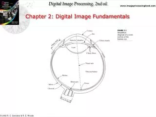
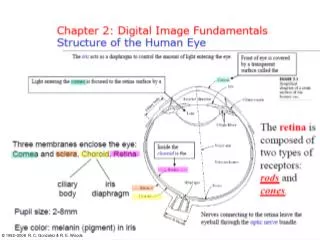
x Origin y f(x,y) Image “After snow storm” Fundamentals of Digital Images wAn image: a multidimensional function of spatial coordinates. wSpatial coordinate: (x,y) for 2D case such as photograph, (x,y,z) for 3D case such as CT scan images (x,y,t) for movies w The functionf may represent intensity (for monochrome images) or color (for color images) or other associated values.
Digital Images Digital image: an image that has been discretized both in Spatial coordinates and associated value. w Consist of 2 sets:(1) a point set and (2) a value set w Can be represented in the form I = {(x,a(x)): xÎX, a(x) ÎF} where X and F are a point set and value set, respectively. w An element of the image, (x,a(x)) is called a pixel where - x is called the pixel location and - a(x) is the pixel value at the location x
Image Sensor:Charge-Coupled Device (CCD) w Used for convert a continuous image into a digital image w Contains an array of light sensors w Converts photon into electric charges accumulated in each sensor unit CCD KAF-3200E from Kodak. (2184 x 1472 pixels, Pixel size 6.8 microns2)
Vertical Transport Register Vertical Transport Register Vertical Transport Register Gate Gate Gate Image Sensor: Inside Charge-Coupled Device Horizontal Transportation Register Output Gate Amplifier Output Photosites
c c f f f i i i b h h b h e e e d d g g g d a a c b a Image Sensor: How CCD works Image pixel Horizontal transport register Vertical shift Output Horizontal shift
Image Types Intensity image or monochrome image each pixel corresponds to light intensity normally represented in gray scale (gray level). Gray scale values
Image Types Color image or RGB image: each pixel contains a vector representing red, green and blue components. RGB components
Image Types Binary image or black and white image Each pixel contains one bit : 1 represent white 0 represents black Binary data
Image Types Index image Each pixel contains index number pointing to a color in a color table Color Table Index value
Image Sampling Image sampling: discretize an image in the spatial domain Spatial resolution / image resolution: pixel size or number of pixels
= Sampling locations How to choose the spatial resolution Spatial resolution Original image Sampled image Under sampling, we lost some image details!
Sampled image Minimum Period Spatial resolution (sampling rate) = Sampling locations How to choose the spatial resolution : Nyquist Rate Original image 1mm 2mm No detail is lost! Nyquist Rate: Spatial resolution must be less or equal half of the minimum period of the image or sampling frequency must be greater or Equal twice of the maximum frequency.
256x256 pixels 128x128 pixels 64x64 pixels 32x32 pixels Effect of Spatial Resolution Down sampling is an irreversible process.
Image Quantization Image quantization: discretize continuous pixel values into discrete numbers Color resolution/ color depth/ levels: - No. of colors or gray levels or - No. of bits representing each pixel value - No. of colors or gray levels Nc is given by where b = no. of bits
Image Quantization : Quantization function Nc-1 Nc-2 Quantization level 2 1 0 Light intensity Darkest Brightest
Effect of Quantization Levels 256 levels 128 levels 64 levels 32 levels
In this image, it is easy to see false contour. Effect of Quantization Levels (cont.) 16 levels 8 levels 4 levels 2 levels
(x-1,y-1) (x,y-1) (x+1,y-1) (x-1,y) (x,y) (x+1,y) (x-1,y+1) (x,y+1) (x+1,y+1) Basic Relationship of Pixels (0,0) x y Conventional indexing method
(x,y-1) (x-1,y) (x+1,y) N4(p) = (x,y+1) Neighbors of a Pixel Neighborhood relation is used to tell adjacent pixels. It is useful for analyzing regions. 4-neighbors of p: (x-1,y) (x+1,y) (x,y-1) (x,y+1) p 4-neighborhood relation considers only vertical and horizontal neighbors. Note: qÎ N4(p) implies pÎ N4(q)
Neighbors of a Pixel (cont.) 8-neighbors of p: (x-1,y-1) (x,y-1) (x+1,y-1) (x-1,y-1) (x,y-1) (x+1,y-1) (x-1,y) (x+1,y) (x-1,y+1) (x,y+1) (x+1,y+1) (x-1,y) p (x+1,y) (x-1,y+1) (x,y+1) (x+1,y+1) N8(p) = 8-neighborhood relation considers all neighbor pixels.
Neighbors of a Pixel (cont.) Diagonal neighbors of p: (x-1,y-1) (x+1,y-1) (x-1,y-1) (x+1,y-1) (x-1,y+1) (x+1,y+1) p ND(p) = (x-1,y+1) (x+1,y+1) Diagonal -neighborhood relation considers only diagonal neighbor pixels.
Template, Window, and Mask Operation Sometime we need to manipulate values obtained from neighboring pixels Example: How can we compute an average value of pixels in a 3x3 region center at a pixel z? Pixel z 2 4 1 2 6 2 9 2 3 4 4 4 7 2 9 7 6 7 5 2 3 6 1 5 7 4 2 5 1 2 2 5 2 3 2 8 Image
Template, Window, and Mask Operation (cont.) Step 1. Selected only needed pixels Pixel z … 2 4 1 2 6 2 9 2 3 4 4 4 3 4 4 … … 7 2 9 7 6 7 9 7 6 5 2 3 6 1 5 3 6 1 7 4 2 5 1 2 … 2 5 2 3 2 8
… 3 4 4 1 1 1 … … 9 7 6 1 1 1 3 6 1 1 1 1 … Template, Window, and Mask Operation (cont.) Step 2. Multiply every pixel by 1/9 and then sum up the values X Mask or Window or Template
Template, Window, and Mask Operation (cont.) Question: How to compute the 3x3 average values at every pixels? Solution: Imagine that we have a 3x3 window that can be placed everywhere on the image 2 4 1 2 6 2 9 2 3 4 4 4 7 2 9 7 6 7 5 2 3 6 1 5 7 4 2 5 1 2 Masking Window
2 4 1 2 6 2 2 4 1 9 2 3 4 4 4 9 2 3 7 2 9 7 6 7 7 2 9 5 2 3 6 1 5 7 4 2 5 1 2 Template, Window, and Mask Operation (cont.) Step 1: Move the window to the first location where we want to compute the average value and then select only pixels inside the window. Step 2: Compute the average value Sub image p Step 3: Place the result at the pixel in the output image Original image 4.3 Step 4: Move the window to the next location and go to Step 2 Output image
1 1 1 1 1 1 1 1 1 w(1,1) w(2,1) w(3,1) w(1,2) w(2,2) w(3,2) w(3,1) w(3,2) w(3,3) Template, Window, and Mask Operation (cont.) The 3x3 averaging method is one example of the mask operation or Spatial filtering. w The mask operation has the corresponding mask (sometimes called window or template). w The mask contains coefficients to be multiplied with pixel values. Example : moving averaging Mask coefficients The mask of the 3x3 moving average filter has all coefficients = 1/9
… p(1,1) p(2,1) p(3,1) … … p(2,1) p(2,2) p(3,2) w(1,1) w(2,1) w(3,1) p(1,3) p(2,3) p(3,3) w(1,2) w(2,2) w(3,2) w(3,1) w(3,2) w(3,3) … Template, Window, and Mask Operation (cont.) The mask operation at each point is performed by: 1. Move the reference point (center) of mask to the location to be computed 2. Compute sum of products between mask coefficients and pixels in subimage under the mask. Mask frame Mask coefficients Subimage The reference point of the mask
Template, Window, and Mask Operation (cont.) The mask operation on the whole image is given by: Move the mask over the image at each location. Compute sum of products between the mask coefficeints and pixels inside subimage under the mask. Store the results at the corresponding pixels of the output image. Move the mask to the next location and go to step 2 until all pixel locations have been used.
-1 -1 1 -1 -2 -1 1 0 1 -1 -1 1 -2 0 -1 1 8 1 0 0 0 2 1 -1 1 1 -1 -1 -1 2 0 1 1 1 1 -1 Template, Window, and Mask Operation (cont.) Examples of the masks Sobel operators 3x3 moving average filter 3x3 sharpening filter