Download
1 / 37
370 likes | 381 Views
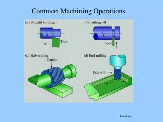
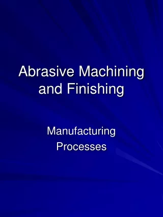
Chapter 26 Abrasive Machining and Finishing Operations. ABRASIVE It is a small hard particle having sharp edges and an irregular shape e.g. sand sand paper and grinding wheels are used to sharpen knives, tools and give good dimensional accuracy and surface finish to products.

E N D
ABRASIVEIt is a small hard particle having sharp edges and an irregular shape e.g. sandsand paper and grinding wheels are used to sharpen knives, tools and give good dimensional accuracy and surface finish to products
FIGURE 26.1 Typical abrasive grains; note the angular shape with sharp edges. (a) A single, 80-mesh Al2O3 grit in a freshly dressed grinding wheel; (b) An 80/100 mesh diamond grit; diamond and cubic boron nitride grains can be manufactured in various geometries, including the “blocky” shape shown.Source: Courtesy of J. Badger.
FIGURE 26.2 A variety of bonded abrasives used in abrasive-machining processes.Source: Courtesy of Norton Company.
FIGURE 26.3 The types of workpieces and operations typical of grinding: (a) cylindrical surfaces; (b) conical surfaces; (c) fillets on a shaft; (d) helical profiles; (e) concave shape; (f) cutting off or slotting with thin wheels; and (g) internal grinding.
Abrasives are harder than cutting tool materialsTYPES OF ABRASIVES1.conventional abrasives: Aluminum oxide (for carbon steel and ferrous alloys)and Silicon carbide (non ferrous metals, glass and marble)2.super abrasives: diamond (ceramics and hardeneded steel) and cubic boron nitride (steels and cast iron)friability: ability of abrasive grains to fracture into smaller pieces. This gives abrasives their self sharpening characteristics essential in maintaining their sharpness during use
GRINDING WHEELSThe abrasives grains are held together by a bonding material in order to achieve high material removal ratesMarking of bonded abrasives51 A 36 L 5 V 23A: abrasive type AL 36 : grain sizeL grade from A (soft) till Z (hard)5: dense from 1-….V: bond type (R:rubber, S:silicate, V:vitrified51 and 23: manufacturer
FIGURE 26.4 Schematic illustration of a physical model of a grinding wheel, showing its structure and its wear and fracture patterns.
FIGURE 26.5 Common types of grinding wheels made with conventional abrasives; note that each wheel has a specific grinding face; grinding on other surfaces is improper and unsafe.
FIGURE 26.6 Examples of superabrasive wheel configurations; the annular regions (rims) are superabrasive grinding surfaces, and the wheel itself (core) generally is made of metal or composites. The bonding materials for the superabrasives are (a), (d), and (e) resinoid, metal, or vitrified; (b) metal; (c) vitrified; and (f) resinoid.
THE GRINDING PROCESSDifference between action of an abrasive grain and that of a single-point cutting tool1. Grains have irregular shapes2. The radial position of a grain on the surface of the wheel varies, so not all grains are active during grinding3. Surface speed of grinding wheels are higher
FIGURE 26.11 Schematic illustration of the surface-grinding process, showing various process variables; the figure depicts conventional (up) grinding.
FIGURE 26.13 Chip formation and plowing of the workpiece surface by an abrasive grain.
GRINDING OPERATIONS AND MACHINESSelection of a grinding process depends upon:1. Shape of work piece2. Its size3. Ease of fixturing4. Production rate required
TABLE 26.4 General Characteristics of Abrasive Machining Processes and Machines
SURFACE GRINDINGwork piece is flatgrinding wheel is mounted on a horizontal spindlework piece is mounted on work tablethe table reciprocates longitudinally and is fed laterallyin the direction of the spindle axis
FIGURE 26.15 Schematic illustrations of various surface-grinding operations. (a) Traverse grinding with a horizontal-spindle surface grinder. (b) Plunge grinding with a horizontal-spindle surface grinder, producing a groove in the workpiece. (c) A vertical-spindle rotary-table grinder (also known as the Blanchard type).
FIGURE 26.16 Schematic illustration of a horizontal-spindle surface grinder.
CYLINDRICAL GRINDINGthe work piece rotates and reciprocates along its axisin roll grinders, the grinding wheel reciprocates
FIGURE 26.18 Examples of various cylindrical-grinding operations: (a) traverse grinding; (b) plunge grinding; and (c) profile grinding. Source: Courtesy of Okuma Corporation. Printed with permission.
FIGURE 26.19 Plunge grinding of a workpiece on a cylindrical grinder with the wheel dressed to a stepped shape.
FIGURE 26.20 Schematic illustration of grinding a noncylindrical part on a cylindrical grinder with computer controls to produce the shape. The part rotation and the distance x between centers are varied and synchronized to grind the particular workpiece shape.
FIGURE 26.21 Thread grinding by (a) traverse and (b) plunge grinding.
INTERNAL GRINDING a small wheel is used in grinding the inside diameter of a partthe work piece is held in a rotating chuck the wheel rotates at a high speed(higher than 30000 r.p.m
FIGURE 26.23 Schematic illustrations of internal grinding operations: (a) traverse grinding; (b) plunge grinding; and (c) profile grinding.
FIGURE 26.27 Schematic illustration of the structure of a coated abrasive; sandpaper (developed in the 16th century) and emery cloth are common examples of coated abrasives.
FIGURE 26.28 Turbine nozzle vane considered in Example 26.5.
WIRE BRUSHINGwork piece is held against a circular wire brush that rotatesthe tips of the wire produce longitudinal scatches on the surface of the work piece
HONINGUsed to improve the surface finish of holesThe honing tool consists of aluminum oxide or silicon carbide bonded abrasive sticks called stonesThe stones can be adjusted radially to suit different hole sizesThe tool has a reciprocating motion
FIGURE 26.29 Schematic illustration of a honing tool used to improve the surface finish of bored or ground holes.
LAPPING Used for finishing cylindrical, flat or curved surfacesThe lap is relatively soft and porous, made of cast iron, leather or clothLapping is done under pressures depending upon the type and hardness of the work piece
FIGURE 26.31 (a) Schematic illustration of the lapping process. (b) Production lapping on flat surfaces. (c) Production lapping on cylindrical surfaces.
POLISHINGProduces a smooth , lustrous surface finishSoftening and smearing of surface layers occur by frictional heating developed during polishing, and by very fine scale abrasive removal from work piece surfacePolishing is done with discs or belts made of fabric or leather, coated with fine powders of aluminum oxide or diamond
DEBURRING OPERATIONSBurrs are thin edges that develop along edges of a work piece due to machining operations or shearing metal sheetsBurrs can be detected with a finger, toothpick or cotton swabDISADVANTAGES OF BURRS1. Interfere with the mechanical assembly of parts2. Unsafe to personnel handling the parts3. May reduce fatigue life of parts4. May cause low bendability if the burr is on the tensile size
FIGURE 26.37 Increase in the cost of machining and finishing a part as a function of the surface finish required; this is the main reason that the surface finish specified on parts should not be any finer than is necessary for the part to function properly.