Download
1 / 29
290 likes | 436 Views
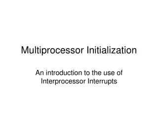
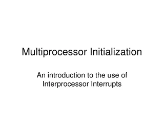
Multiprocessor Initialization. An introduction to the use of Interprocessor Interrupts. A traditional MP system. Main memory. CPU 0. CPU 1. system bus. Dual-Core Technology. Core 2 Duo processor. Main memory. CPU 0. CPU 1. Shared level-2 cache. system bus. Multi-Core Technology.

E N D
Multiprocessor Initialization An introduction to the use of Interprocessor Interrupts
A traditional MP system Main memory CPU 0 CPU 1 system bus
Dual-Core Technology Core 2 Duo processor Main memory CPU 0 CPU 1 Shared level-2 cache system bus
Multi-Core Technology Core 2 Quad processor Main memory CPU 0 CPU 1 CPU 2 CPU 3 Shared level-2 cache Shared level-2 cache system bus
CPU has its own Local-APIC CPU processor’s application registers EAX, EBX, …, EIP, EFLAGS processor’s system registers CR0, CR2, CR3, …, IDTR, GDTR, TR processor’s Execution Engine processor’s Local-APIC registers Local-ID, IRR, ISR, EOI, LVT0, LVT1, …, ICR, TCFG
The Local-APIC ID register 31 24 0 reserved APIC ID This register is initially zero, but its APIC ID Field (8-bits) is programmed by the BIOS during system startup with a unique processor identification- Number, which subsequently is used when specifying the processor as a recipient of inter-processor interrupts. Memory-Mapped Register-Address: 0xFEE00020
The Local-APIC EOI register 31 0 write-only register This write-only register is used by Interrupt Service Routines to issue an ‘End-Of-Interrupt’ command to the Local-APIC. Any value written to this register will be interpreted by the Local-APIC as an EOI command. The value stored in this register is initially zero (and it will remain unchanged). Memory-Mapped Register-Address: 0xFEE000B0
The Spurious Interrupt register 31 8 7 0 reserved E N spurious vector Local-APIC is Enabled (1=yes, 0=no) This register is used to Enable/Disable the functioning of the Local-APIC, and when enabled, to specify the interrupt-vector number to be delivered to the processor in case the Local-APIC generates a ‘spurious’ interrupt. (In some processor-models, the vector’s lowest 4-bits are hardwired 1s.) Memory-Mapped Register-Address: 0xFEE000F0
Interrupt Command Register • Each processor’s Local-APIC unit has a 64-bit Interrupt Command Register • It can be programmed by system software to transmit messages to one, or to several, of the other processors in the system • Each processor has a unique identification number in its APIC Local-ID Register that can be used for directing messages to it
ICR (upper 32-bits) 31 24 0 reserved Destination field The Destination Field (8-bits) can be used to specify which processor (or group of processors) will receive the message Memory-Mapped Register-Address: 0xFEE00310
ICR (lower 32-bits) 15 31 19 18 12 10 8 7 0 R / O Vector field Delivery Mode 000 = Fixed 001 = Lowest Priority 010 = SMI 011 = (reserved) 100 = NMI 101 = INIT 110 = Start Up 111 = (reserved) Destination Shorthand 00 = no shorthand 01 = only to self 10 = all including self 11 = all excluding self Trigger Mode 0 = Edge 1 = Level Level 0 = De-assert 1 = Assert Destination Mode 0 = Physical 1 = Logical Delivery Status 0 = Idle 1 = Pending Memory-Mapped Register-Address: 0xFEE00300
MP initialization protocol • Set a shared processor-counter equal to 1 • Step 1: issue an ‘INIT’ IPI to all-except-self • Delay for 10 milliseconds • Step 2: issue ‘Startup’ IPI to all-except-self • Delay for 200 microseconds • Step 3: issue ‘Startup’ IPI to all-except-self • Delay for 200 microseconds • Check the value of the processor-counter
Issue an ‘INIT’ IPI # address Local-APIC via register FS mov $sel_fs, %ax mov %ax, %fs # broadcast ‘INIT’ IPI to ‘all-except-self’ mov $0x000C4500, %eax mov %eax, %fs:0xFEE00300) .B0: btl $12, %fs:(0xFEE00300) jc .B0
Issue a ‘Startup’ IPI # broadcast ‘Startup’ IPI to all-except-self # using vector 0x11 to specify entry-point # at real memory-address 0x00011000 mov $0x000C4611, %eax mov %eax, %fs:(0xFEE00300) .B1: btl $12, %fs:(0xFEE00300) jc .B1
Timing delays • Intel’s MP Initialization Protocol specifies the use of some timing-delays: • 10 milliseconds ( = 10,000 microseconds) • 200 microseconds • We can use the 8254 Timer’s Channel 2 for implementing these timed delays, by programming it for ‘one-shot’ countdown mode, then polling bit #5 at i/o port 0x61
Mathematical examples EXAMPLE 1 Delaying for 10-milliseconds means delaying for 1/100-th of a second (because 100 times 10-milliseconds = one-thousand milliseconds) EXAMPLE 2 Delaying for 200-microseconds means delaying 1/5000-th of a second (because 5000 times 200 microseconds = one-million microseconds) GENERAL PRINCIPLE Delaying for x–microseconds means delaying for 1000000/x seconds (because 1000000/x times x-microseconds = one-million microseconds)
Mathematical theory PROBLEM: Given the desired delay-time in microseconds, express the desired delay-time in clock-frequency pulses and program that number into the PIT’s Latch-Register RECALL: Clock-Frequency-in-Seconds = 1193182 Hertz ALSO: One second equals one-million microseconds APPLYING DIMENSIONAL ANALYSIS Pulses-Per-Microsecond = Pulses-Per-Second / Microseconds-Per-Second Delay-in-Clock-Pulses = Delay-in-Microseconds * Pulses-Per-Microsecond CONCLUSION For a desired time-delay of x microseconds, the number of clock-pulses may be computed as x * (1193182 /1000000) = (1193182 * x) / 1000000 as dividing by a fraction amounts to multiplying by that fraction’s reciprocal
Delaying for EAX microseconds # We compute the value for the 8254 Timer’s Channel-2 Latch-register # Delaying for EAX microseconds means that Latch-register’s value is # a certain fraction of one full second’s worth of input-pulses: # fraction = (EAX microseconds)/(one-million microseconds-per-second) # # Thus the latch-value should be: fraction*(1193182 pulses-per-second) # which we can compute by doing a multiplication followed by a division # mov %eax, %ecx # copy the delay to ECX mov $1193182, %eax # setup input-frequency in EAX mul %ecx # multiplied by microseconds mov $1000000, %ecx # setup one-million as a divisor div %ecx # so quotient will be Latch-value # Quotient in register AX should be written to the timer’s Latch Register
Intel’s MP terminology • When an MP system starts up, one of the CPUs will be selected to handle the ‘boot’ procedures, while the other CPUs ‘sleep’ • The BSP is this BootStrap Processor, and every other processor is known as an AP (i.e., a so-called ‘Application Processor’) BSP AP AP AP
‘parallel computing’ principles • When it’s awakened, each processor will need its own private stack-area, so it can handle any interrupts or procedure-calls without modifying an area in memory which another processor is also using • And whenever two or more processors do share ‘write-access’ to any memory area, then those accesses must ‘serialized’
‘atomic’ memory-access • Shared variables must not be modified by more than one processor at a time (‘atomic’ access) • The x86 cpu’s ‘lock’ prefix helps enforce this • Example: every processor adds 1 to a counter lock incl (counter) • Some instructions have ‘atomic’ access built in • Example: all processors needs private stacks mov 0x1000, %ax xadd (new_SS), %ax mov %ax, %ss
ROM-BIOS isn’t ‘reentrant’ • The video service-functions in ROM-BIOS often used to display a message-string at the current cursor-location (and afterward advance the cursor) modify global storage locations (as well as i/o ports), and hence must be called by one processor at a time • A shared memory-variable (called ‘mutex’) is used to enforce this mutual exclusion
Implementing a ‘spinlock’ # Here is a ‘global’ variable, which all of the processors can modify mutex: .word 1 # initial value for variable is 1 # Here is a ‘prologue’ and ‘epilog’ for using this variable to enforce # ‘mutually exclusive access’ to a section of ‘non-reentrant’ code spin: btw $0, mutex # test bit #0 to see if mutex is free jnc spin # spin if the mutex is not available lock # else request exclusive bus-access btrw $0, mutex # and try to grab mutex ownership jnc spin # unsuccessful? then try again < CRITICAL SECTION OF ‘NON-REENTRANT’ CODE> btsw $0, mutex # release the mutex when finished
Demo: ‘mphello.s’ • Each CPU needs to access its Local-APIC • The BSP (“Boot-Strap Processor”) wakes up other processors by broadcasting the ‘INIT-SIPI-SIPI’ message-sequence • Each AP (“Application Processor”) starts executing at a 4K page-boundary -- and needs its own private stack-area • Shared variables require ‘atomic’ access
Demo’s organization MAIN: # the BSP will execute these calls call allow_4GB_access call display_APIC_LocalID call broadcast_AP_starup call delay_until_APs_halt initAP: # each AP will execute these calls call allow_4GB_access call display_APIC_LocalID
In-class exercise #1 • Add a call to this procedure by each of the processors, but do it without using a ‘lock’ prefix (and outside mutex-protected code) • Then let the BSP print the value of ‘total’ total: .word 0 # include this ‘shared’ global-variable add_one_thousand: # let each processor call this subroutine mov $1000, %cx nxadd: addw $1, total loop nxadd ret
Binary-to-Decimal • Recall algorithm for converting numbers to decimal digit-strings (for console display) num2dec: # converts value in register AX to a decimal string at DS:DI mov $10, %bx # setup the number-base in BX xor %cx, %cx # setup remainder-count in CX nxdiv: xor %dx, %dx # extend AX to a doubleword div %bx # divide the doubleword by ten push %dx # save remainder on the stack inc %cx # and count this remainder or %ax, %ax # was the quotient zero yet? jnz nxdiv # no, generate another digit nxdgt: pop %dx # recover saved remainder add $’0’, %dl # convert remainder to ASCII mov %dl, (%di) # store numeral in output-buffer inc %di # and advance buffer-pointer loop nxdgt # again for other remainders
In-class exercise #2 • Using a Core-2 Quad processor we might expect the value of ‘total’ would be 4000 • But see if that’s what actually happens! • Without the ‘lock’ prefix, the four CPUs may all try to increment ‘total’ at once, resulting in a logically incorrect total • So fix this problem (by using a ‘lock’ prefix ahead of the ‘addw $1, total’ instruction)
Do you need a ‘barrier’? • You can use a software construct, known as a ‘barrier’, to stop CPUs from entering a block of code until a prescribed number of them are all ready to enter it together (i.e., simultaneously) • This may be helpful with the in-class exercises arrived: .word 0 # allocate a shared global variable barrier: lock # acquire exclusive bus-access incw arrived # each cpu adds 1 to the variable await: cmpw $4, arrived # are four cpus ready to proceed? jb await # no, wait for others to arrive here call add_one_thousand # then proceed together