Download
1 / 55
580 likes | 809 Views
Advanced Computer Graphics Three Dimensional Viewing. Overview. Viewing a 3D scene Projections Parallel and perspective. Overview. Surface rendering. Overview. Exploded and cutaway views. Overview. 3D and stereoscopic viewing. 3D Viewing Pipeline. MC. DC. Viewport Transformation.

E N D
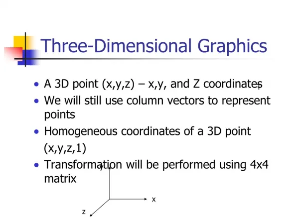
Overview • Viewing a 3D scene • Projections • Parallel and perspective
Overview • Surface rendering
Overview • Exploded and cutaway views
Overview • 3D and stereoscopic viewing
3D Viewing Pipeline MC DC ViewportTransformation ModelingTransformation NC WC Normalization Transformation and Clipping ViewingTransformation VC PC ProjectionnTransformation
Viewing Coordinates • Generating a view of an object in 3D is similar to photographing the object. • Whatever appears in the viewfinder is projected onto the flat film surface. • Depending on the position, orientation and aperture size of the camera corresponding views of the scene is obtained.
xv yv yw zv P0=(x0 , y0 , z0) xw zw Specifying The View Coordinates • For a particular view of a scene first we establishviewing-coordinate system. • Aview-plane (orprojection plane)is set up perpendicular to the viewing z-axis. • World coordinates are transformed to viewing coordinates, then viewing coordinates are projected onto the view plane.
Specifying The View Coordinates • To establish the viewing reference frame, we first pick a world coordinate position called the view reference point. • This point is the origin of our viewing coordinate system. If we choose a point on an object we can think of this point as the position where we aim a camera to take a picture of the object.
Specifying The View Coordinates • Next, we select the positive direction for the viewing z-axis, and the orientation of the view plane, by specifying the view-plane normal vector, N. • We choose a world coordinate position P and this point establishes the direction forN. • OpenGL establishes the direction for N using the point P as a look at point relative to the viewing coordinate origin. yv xv xv yw zv N P0 P xw zw
Specifying The View Coordinates • Finally, we choose the up direction for the view by specifying view-up vector V. • This vector is used to establish the positive direction for the yvaxis. • The vector V is perpendicular to N. • Using N and V, we can compute a third vector U, perpendicular to both N and V, to define the direction for the xv axis. yv xv V yw zv N P0 P xw zw
Specifying The View Coordinates V To obtain a series of views of a scene , we can keep the the view reference point fixed and change the direcion of N. This corresponds to generating views as we move around the viewing coordinate origin. P0 N N
yv xv zv Transformation From World To Viewing Coordinates Conversion of object descriptions from world to viewing coordinates is equivalent to transformation that superimpoes the viewing reference frame onto the world frame using the translation and rotation. yw xw zw
yv xv zv Transformation From World To Viewing Coordinates First, we translate the view reference point to the origin of the world coordinate system yw xw zw
yv xv zv yv zv Transformation From World To Viewing Coordinates Second, we apply rotations to align the xv,, yv and zv axes with the world xw, yw and zw axes, respectively. yw xw xv zw
Transformation From World To Viewing Coordinates If the view reference point is specified at word position (x0, y0, z0), this point is translated to the world origin with the translation matrix T.
Transformation From World To Viewing Coordinates • The rotation sequence requires 3 coordinate-axis transformation depending on the direction of N. • First we rotatearound xw-axis to bring zv into the xw -zw plane.
Transformation From World To Viewing Coordinates Then, we rotate around the world ywaxis to align the zwand zv axes.
Transformation From World To Viewing Coordinates The final rotation is about the world zwaxis to align the ywand yv axes.
Transformation From World To Viewing Coordinates The complete transformation from world to viewing coordinate transformation matrix is obtaine as the matrix product
Transformation From World To Viewing Coordinates: An Example For 2d System y 2 P=(5,5) y′ x′ 2 0 2 4 6 Θ=300 P0=(4,3) 0 2 4 6 x
Transformation From World To Viewing Coordinates: An Example For 2d System Translation: y 0 2 4 6 P 2 x′ 2 y′ Θ=300 2 4 6 x P0
y y′ P x′ 2 4 6 x P0 Transformation From World To Viewing Coordinates: An Example For 2d System Rotation 0 2 4 6
Transformation From World To Viewing Coordinates: An Example For 2d System New coordinates
Transformation From World To Viewing Coordinates: An Example For 2d System Alternative Method y 0 1 2 3 P 1 x′ y′ 1 n v Θ=300 x 1 2 3 P0
Projections • Once WC description of the objects in a scene are converted to VC we can project the 3D objects onto 2D view-plane. • Two types of projections: -Parallel Projection -Perspective Projection
Classical Viewings • Hand drawings : Determined by a specificrelationship between the object and the viewer.
Parallel Projections Coordinate Positions are transformed to the view plane along parallel lines. View Plane P2 P′2 P1 P′1
Parallel Projections • Orthographic parallel projection The projection is perpendicular to the view plane. • Oblique parallel projecion The parallel projection is not perpendicular to the view plane.
Oblique Parallel Projection • The projectors are still ortogonal to the projection plane • But the projection plane can have any orientation with respect to the object. • It is used extensively in architectural and mechanical design.
Oblique Parallel Projection • Preserve parallel lines but not angles • Isometric view : Projection plane is placed symmetrically with respect to the threeprincipal faces that meet at a corner of object. • Dimetric view : Symmetric with two faces. • Trimetric view : General case.
Oblique Parallel Projection • Preserve parallel lines but not angles • Isometric view : Projection plane is placed symmetrically with respect to the threeprincipal faces that meet at a corner of object. • Dimetric view : Symmetric with two faces. • Trimetric view : General case.
Perspective Projections • First discovered by Donatello, Brunelleschi, and DaVinci during Renaissance • Objects closer to viewer look larger • Parallel lines appear to converge to single point
Perspective Projections In perspective projection object positions are transformed to the view plane along lines that converge to a point called the projection reference point (or center of projection)
Perspective Projections • In the real world, objects exhibit perspective foreshortening: distant objects appear smaller • The basic situation:
How tall shouldthis bunny be? Perspective Projections When we do 3-D graphics, we think of the screen as a 2-D window onto the 3-D world:
X P (x, y, z) x′ = ? (0,0,0) Z Perspective Projections The geometry of the situation is that of similar triangles. View from above: View plane (xp, yp) d
Perspective Projections Desired result for a point [x, y, z, 1]T projected onto the view plane:
View Volumes • When a cameraused to take a picture, the type of lens used determines how much of the scene is caught on the film. • In 3D viewing, a rectangular view window in the view plane is used to the same effect. Edges of the view window are parallel to the xv-yv axes and window boundary positions are specified in viewing coordinates.
View Volumes View volume View volume (frustum) zv window Back Plane window Front Plane Back Plane Projection Reference Point Front Plane Parallel Projection Parallel Projection Perspective Projection
Clipping • An algorithm for 3D clipping identifies and saves all surface segments within the view volume for display. • All parts of object that are outside the view volume are discarded.
Clipping Lines Just like the case in two dimensions, clipping removes objects that will not be visible from the scene The point of this is to remove computational effort 3-D clipping is achieved in two basic steps • Discard objects that can’t be viewed • i.e. objects that are behind the camera, outside the field of view, or too far away • Clip objects that intersect with any clipping plane
Discard Objects Discarding objects that cannot possibly be seen involves comparing an objects bounding box/sphere against the dimensions of the view volume • Can be done before or after projection
Clipping Polygon Surface • To clip a polygon surface, we can clip the individual polygon edges. • First we test the coordinate extends against each boundary of the view volume to determine whether the object is completely inside or completely outside of that boundary. • If the object has intersection with the boundary then we apply intersection calculations.
Clipping Polygon Surface • The projection operation can take place before the view- volume clipping or after clipping. • All objects within the view volume map to the interior of the specified projection window. • The last step is to transform the window contents to a 2D view port.
Normalisation The transformed volume is then normalised around position (0, 0, 0) and the z axis is reversed
Dividing Up The World Similar to the case in two dimensions, we divide the world into regions This time we use a 6-bit region code to give us 27 different region codes The bits in these regions codes are as follows:
3D Line Clipping Example (cont…) When then simply continue as per the two dimensional line clipping algorithm