Download
1 / 54

E N D
UNIT II SWITCHING TRANSIENTS Over voltages due to switching transients - resistance switching and the equivalent circuit for interrupting the resistor current - load switching and equivalent circuit - waveforms for transient voltage across the load and the switch - normal and abnormal switching transients. Current suppression - current chopping – effect ive equivalent circuit. Capacitance switching - effect of source regulation - capacitance switching with a restrike, with multiple restrikes. Illustration for multiple restriking transients - ferro resonance.
INTRODUCTION • A transient occurs in the power system when the network changes from one steady state into another. • The majority of power system transients is, however, the result of a switching action. Load break switches and disconnectors switch off and switch on parts of the network under load and no-load conditions. • Fuses and circuit breakers interrupt higher currents and clear short-circuit currents flowing in faulted parts of the system. • The time period when transient voltage and current oscillations occur is in the range of microseconds to milliseconds.
OVERVOLTAGE • An overvoltage is an increase in the r.m.s. ac voltage greater than 110 % at the power frequency for a duration longer than 1 min. • It is a result of load switching. Eg : Switching OFF a Large load Energizing a capacitor bank
Switchings in a power system occur frequently. • A variety of switchings are performed for routine operations or automatically by control and protection systems. • Typical switchings are as follows: • Lines (transmission or distribution) • Cables • Shunt/series capacitors • Shunt reactors • Transformers • Generators/motors
OVER VOLTAGES • The causes of power system over voltages are numerous and the waveforms are complex. • It is customary to classify the transients on the basis of frequency content of the waveforms. • In this sense, the following three broad categories are defined: • Power frequency overvoltages • Switching overvoltages • Lightning overvoltages
How does Resistance Switching Work • Let us consider a circuit and connect a shunt resistance R across the contacts of the breaker as shown . Suppose a fault occurs on the line. Because of the occurrence of fault, the contacts of breaker will open and an arc will stuck between the contacts.
Since the contacts of breaker are shunted by resistance R, therefore a part of arc current will flow through this resistance R. Due to this the magnitude of arc current will reduce which in turn will result in increase in the rate of de-ionization of arc path. In this way, the arc resistance increases. This increased arc resistance leads to further increases in the current through the shunt resistance R. • Thus again, the arc current will reduce and hence the arc resistance increases. This cumulative process will continue till the magnitude of arc current becomes so low that it is not able to maintain the arc. Thus the arc extinguishes and the current is interrupted by the breaker. • Resistance Switching also reduces the oscillatory growth of Re-striking Voltage. The natural frequency of the circuit shown above is given by fn = (1/2π)√(1/LC – 1/4R2C2) • The main role of shunt resistance R is to limit the growth of re-strike voltage and cause it to grow exponentially up to recovery voltage. If the value of R is so selected that the circuit becomes critically damped then re-strike voltage rises exponentially till recovery voltage is reached.
OBJECTIVES i) To reduce switching surges and over voltages ii) For potential control access multi-breakers per phase in the high voltage breakers iii) To reduce natural frequencies effects and breaker recovery voltage
NEED FOR RESISTANCE SWITCHING • The shunt resistors connected across circuit breaker have two functions: • To distribute the transient recovery voltage more uniformly across the several breaks. ii) To reduce the severity of transient recovery voltage at the time of interruption by introducing damping into oscillation.
Thus the advantages of resistance switching are as follows: • It reduces the rate of rise of re-striking voltage and the peak value of re-striking voltage. • Resistance Switching helps to reduce the voltage transient surge during current choppingand capacitive current breaking.
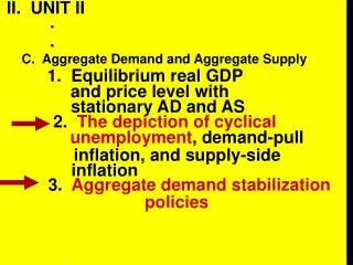
Normal switching transientsare circumstances in which voltage or current within the normal peak values Closing switch or circuit in a dominantly capacitive or inductive network results in inrush currents which can cause problems for the protection system. Abnormal switching transients are circumstances in which voltage or current are far in excess of twice in normal peak values. Insulation of high voltage circuit breakers typically can over voltages up to 2.5 times over its normal voltage.
Capacitor Switching • Capacitor switching is one of the most common switching events on utility systems. • Capacitors are used to provide reactive power (in units of vars) to correct the power factor, which reduces losses and supports the voltage on the system. • They are a very economical and generally trouble-free means of accomplishing these goals. • Alternative methods such as the use of rotating machines and electronic var compensators are much more costly or have high maintenance costs.
One drawback to the use of capacitors is that they yield oscillatory transients when switched. • Some capacitors are energized all the time (a fixed bank), while others are switched according to load levels. • Various control means, including time, temperature, voltage, current, and reactive power, are used to determine when the capacitors are switched. • It is common for controls to combine two or more of these functions, such as temperature with voltage override.
One of the common symptoms of power quality problems related to utility capacitor-switching overvoltages is that the problems appear at nearly the same time each day. • On distribution feeders with industrial loads, capacitors are frequently switched by time clock in anticipation of an increase in load with the beginning of the working day. • Common problems are adjustable speed-drive trips and malfunctions of other electronically controlled load equipment that occur without a noticeable blinking of the lights or impact on other, more conventional loads.
Restrikes During Capacitor De-Energizing • When a grounded capacitor bank is energized using a mechanical oil filled switch, the switching is most likely to occur at or near the system voltage peak. • At this instant, the capacitor voltage is zero while the system voltage is near maximum. • The largest potential difference between contacts is 1.0 pu. • Due to the slow-moving nature of the mechanical switch and the large potential difference, insulation across the switch contacts tends to break down giving rise to an electric arc. • It allows capacitive current to flow, thereby energizing the capacitor before the actual switch contacts close or touch. This phenomenon is known as pre-strike.
It occurs in many types of switches without closing control. • It is usually considered as a natural behavior of the switch and should not raise any concern because capacitor voltage prior to energizing is negligible. • The resulting peak transient voltage is no worse than that when the capacitor is intentionally energized at the system voltage peak.
On the other hand, restrikes (or reignitions) during capacitor deenergizing do rise concerns. • Restrikes or reignitions occur when arcs between parting contacts are re-established after initial current extinction causing unintended re-energizing of the capacitor. • Because of the trapped charges following the initial extinction, significant overvoltage well above 2 pu can result. • It should be noted that a successful capacitor deenergizing (i.e., no restrike) does not normally yield any transient overvoltage.
Restrikes can occur multiple times and in succession over a short time period. • It can also be intermittent over a longer time span. In either circumstance, a restrike poses problems to the power system as well as to the switching device itself.
Capacitance Switching Off • Disconnect: C /unload Transmission lines • Concerns: reignite/restrike in opening • Chance low, Cap. Sw. frequent • Cap fully charged • Half Cycle VCB=2 Vp
Discussion Cap. Sw. Off • In fact Vc>Vsys Ferranti Rise • Vsource_side decrease to Vsys • There is a ∆V change (however,exist in weak systems) • Discon. a C.B. in lower side of step down Transformer supplying an unloaded cable • Current in Cap. Sw. is freq. small and it is possible to disconnect it In first zero -- with small contact sep., 2 V appear across contacts --- increased possibility of restrike (small separation) • Oscillating to new voltage with f0=1/2Π√LC • I(restrike)=2Vp/√L/C sinω0t • Transient peak of 3 Vp
Capacitor Switching …continued • A 13.8 KV, 5000KVAR, 3ph bank,NGr • Source Gr, inductance:1 mH • Restrike at Vp: 1- c=5/(377x13.8)=69.64μF 2- Z=√1000/69.64=3.789Ω 3-Ip=2√2x13.8/(√3x3.789)=5.947 KA 4-f0=603 Hz
FERRO RESONANCE - DEFINITION • The term Ferro resonance refers to a special kind of resonance that involves capacitance and iron-core inductance. The most common condition in which it causes disturbances is when the magnetizing impedance of a transformer is placed in series with a system capacitor. This happens when there is an open-phase conductor. Under controlled conditions, ferro resonance can be exploited for useful purpose such as in a constant-voltage transformer
Ferro resonance- Occurence • Nonlinear resonance between unloaded transformer magnetizing branch and a series capacitor • May occur when distribution transformers fed from cables are switched one phase at a time • Especially a problem on ungrounded star-delta transformers • May occur any time an unloaded iron-core coil is in series with a capacitor
Long-duration overvoltage caused by ferroresonance of transformer
Ferro resonance is different than resonance in linear system elements. In linear systems, resonance results in high sinusoidal voltages and currents of the resonant frequency. • Ferro resonance can also result in high voltages and currents, but the resulting waveforms are usually irregular and chaotic in shape.