Download
1 / 41
410 likes | 582 Views
Active Beam Spectroscopy in Hot Fusion Plasmas (Introduction). Manfred von Hellermann FOM Institute for Plasma Physics Rijnhuizen, NL. Seminar-I Institute for Plasma Physics Academy of Sciences Hefei, China May, 5, 2007. Acknowledgement:

E N D
Active Beam Spectroscopy in Hot Fusion Plasmas (Introduction) Manfred von Hellermann FOM Institute for Plasma Physics Rijnhuizen, NL Seminar-I Institute for Plasma Physics Academy of Sciences Hefei, China May, 5, 2007 Acknowledgement: CXRS groups at JET, TEXTOR, Tore Supra , ASDEX-UG and members of the ITPA expert group on Active Beam Spectroscopy
M. von Hellermann • Introduction to Active Beam Spectroscopy • Spectral Analysis, Evaluation and Simulation Codes • Beam Emission Spectroscopy and MSE
Outline • Basic concepts of active beam spectroscopy (CXRS + BES) • CXRS on JET • Global Consistency Checks based on CXRS • CXRS and BES on ITER making use of a DNB M. von Hellermann
CXRS Aims : 1) Helium ash measurement 2) Impurity ion densities 3) Fuel mixture and density 4) Plasma rotation 5) Ion temperature 6) Particle transport studies BES & MSE Aims : 1) Localisation of active volume 2) Local Beam Density (BES) 3) Density Fluctuations(BES) 4) Local pitch angle (MSE) 5) Local Lorentz field (MSE) M. von Hellermann
Active Beam Spectroscopy ( basic principles) • localized measurement • quantitative use of intensities • intrinsic consistency of temperature, rotation and density • advanced collisional radiative atomic modelling • beam emission spectroscopy as indispensable collateral to CXRS • BES and MSE M. von Hellermann
Courtesy: Carine Giroud M. von Hellermann
D-CXRS Beam Emission Spectroscopy on TEXTOR M. von Hellermann
Beam Emission Spectroscopy as tool for absolute calibration of CXRS signals Combination of CXRS and BES: common line of sight and beam geometry M. von Hellermann
Combination of CXRS and BES enables deduction of ion densities without absolute calibration and measurement of optical transmission local concentration measurements reduced to a line ratio measurement Note: Atomic rates Q depend on energy, electron and ion densities and temperatures M. von Hellermann
Ion Temperarure deduced from Doppler width. • Velocity can be deduced from Doppler shift • Density can be deduced from measured intensity • <Zeff> can be deduced from • continuum background Ion Temperature, Velocity and Density measurement Reference line v Ti For global consistency all physics parameters extracted simultaneously from CX spectrum including its baseline need to be validated M. von Hellermann
D0+C6+ -> D+ + C5+ (n=8 -> n=7) D0+Be4+ -> D+ + Be3+ (n=6 -> n=5) D0+He2+ -> D+ + He+ (n=4 -> n=3) Intensity of Charge-exchange emission Variation of the cross-section with beam energy Effective CX emission Rates provided by ADAS http://adas.phys.strath.ac.uk M. von Hellermann
Core CXRS diagnostic at JET • Spatial resolution: limited by l.o.s. intersection of flux surfaces in beam volume • Time resolution: limited by detector readout ~50ms. Courtesy: Carine Giroud
Parasitic emission to active charge-exchange emission • Parasitic emission: • electron impact and passive CX emission of other species coming from the edge of the plasma. C5+ charge-exchange spectra Be1+ electron impact C2+ electron impact M. von Hellermann
Parasitic emission to active charge-exchange emission • Parasitic emission: • passive charge-exchange with thermal deuterium neutrals C5+active CX C5+passive CX Top view of torus Line of sight Neutral beam Zone of high passive charge-exchange M. von Hellermann
Some JET CXRS results M. von Hellermann
Courtesy: Carine Giroud Example of the use of Charge Exchange measurements Internal transport barrier #51976 M. von Hellermann
Example of the use of Charge Exchange measurements • Impurity transport studies Crucial to study impurity behaviour Low and high Z impurity: fuel dilution (He ash) High Z : radiative collapse Courtesy: Carine Giroud M. von Hellermann
CHEAP • Charge Exchange Analysis Package • Mapping of physics quantities on symmetrised • coordinates (magnetic flux surface indices) • Monitoring of main low-Z ions including bulk ions • Self consistent calculation of beam-target interaction processes • Primary data consistency checks (effective ion charge, kinetic plasma energy, neutron yield M. von Hellermann
JET pulse #61388 Zeff contributions from C+6, Ar+16 and Ar+18 M. von Hellermann
Zeff-Visible Bremsstrahlung (Abel inverted) Zeff reconstructed from C+6, Ar+16 and Ar+18 M. von Hellermann
Reconstruction of Thermal and Beam -Thermal Neutron yield in DT plasma M. von Hellermann
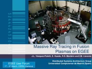
Diagnostic beam for ITER: E=100keV/amu, P=3.6MW, div=10mrad, distance to blanket opening 19.2m Chris Walker, ITER CT
Table II 200 keV, 50 A D beam Source Dimensions : Y = 1.53 m (high) and X =0.58 m Divergence of the main beam : 10 mrad Case Fx (m) Fy (m) Aperture location (m) Aperture dimensions Divergence (85% main beam) Halo component (15% main beam Fractional power transmitted Launched power (MW) Power at observation point (MW) Current (A) X’(m) Y’(m) (mrad) (mrad) ’ (mrad) ’ (mrad) I II III 21.5 19.2 19.2 19.2 21.5 19.2 19.2 19.2 19.2 0.108 0.108 0.108 0.108 0.108 0.108 10 10 10 10 10 10 30 30 30 30 30 30 0.283 0.275 0.29 6 6 6 1.7 1.65 1.74 8.5 8.25 8.7 Courtesy: Drs M.Singh, S.Mattoo, Institute for Plasma Research, India M. von Hellermann M. von Hellermann
Conceptual optics design for ITER Core-CXRS U-port periscope combining neutron labyrinth and Cassegrain output optics Double Vacuum Window Cassegrain output to fibres Fibres to spectrometers Adjustment mechanism Rear of periscope full view of DNB path (2m) M. von Hellermann
Step 4 • Placing of upper shielding blocks • Connection blocks to cooling system Shielding block Optics layer TNO periscope design: “Central Removable Tube” containing First-Mirror and Shutter Friso Klinkhamer, TNO Shielding block M. von Hellermann
Proposed active (focussed on DNB) andpassive (off-beam) fibre bundles M. von Hellermann
TRINITI Spectrometer ITER CXRS proto-type spectrometer developed by TRINITI, Troitsk, RF Echelle 15th order, F/3, f=500mm, 0.25nm/mm M. von Hellermann
Littrow spectro + Pixelvision ccd TRINITI spectro + Pixis 400B ccd # 104461CVI @ 5290Asame line of sight Red: during NBIBlue: before NBI M. von Hellermann M. von Hellermann
ITER CXRS measurement requirement table M. von Hellermann
Simulated Continuum level, fluctuation and HeII signal strength for ITER U-port 2 (left) and U-port-3 (right) U-port-3 continuum level is slightly below U-port-2 level due to shorter path length through plasma M. von Hellermann
Error Analysis for simulated HeII spectra, ITER Upper-port-2, t=100ms, Doppler width and shift deduced from simultaneously analysed CVI
DNB induced MSE and CXRS spectrum , B=5.3T, E=100keV/amu s0 D-alpha-edge s+ s- D-alpha-CX p+3 p+4 p+2 p-2 p-3
MSE and CXRS on D error analysis M. von Hellermann
Summary remarks Active Beam Spectroscopy offers a rich diagnostic potential for present and future fusion experiments Substantial progress has been achieved in a quantitative analysis of active spectra and results are considered as indispensable input for plasma interpretation codes Advanced atomic modelling and self consistent analysis procedures have led to a general acceptance of CXRS as a reliable diagnostic and plasma control tool Future fusion devices as ITER do envisage the use of CXRS with challenging demands on components and beam sources M. von Hellermann