Download
1 / 55
550 likes | 654 Views
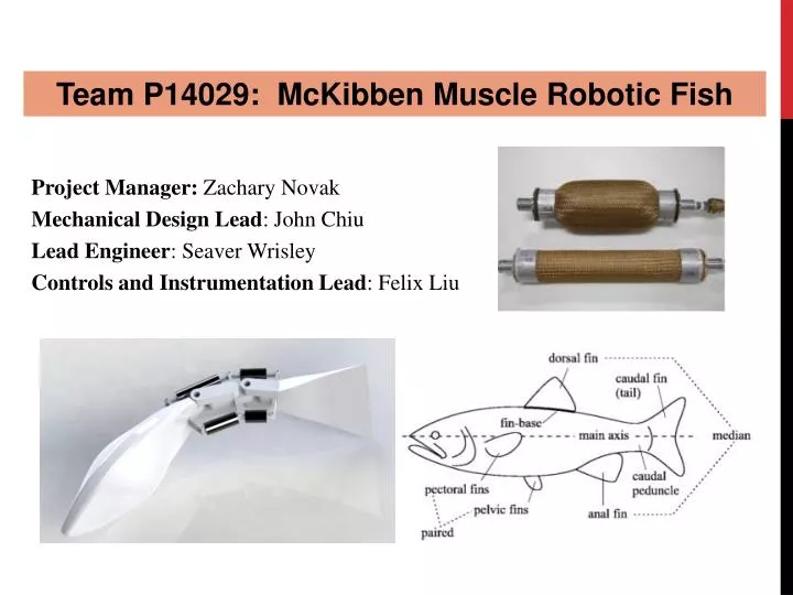
Team P14029: McKibben Muscle Robotic Fish. Project Manager: Zachary Novak Mechanical Design Lead : John Chiu Lead Engineer : Seaver Wrisley Controls and Instrumentation Lead : Felix Liu. Agenda. Project Background Problem Statement Deliverables Updates to Engineering Reqs

E N D
Team P14029: McKibben Muscle Robotic Fish Project Manager: Zachary Novak Mechanical Design Lead: John Chiu Lead Engineer: Seaver Wrisley Controls and Instrumentation Lead: Felix Liu
Agenda • Project Background • Problem Statement • Deliverables • Updates to Engineering Reqs • Feedback from Last Review • Concept Breakdown • Internal System Diagram • Subsystem Identification • Critical Subsystem Identification • Orientation Control Feasibility • Buoyancy Calculations • Design Concept • Power System Feasibility • Power Flow Analysis • Power Source Selection • Battery Life Analysis • Propulsion System Feasibility • Pressure Drag Calculations • McKibben Muscle Test Results • Control System Feasibility • Electronics Schematic • Logic Flow Chart • Microprocessor Options/Selection • Solenoid Options/Selection • Solenoid Control Circuit Schematic • Kinematic Analysis • Preliminary Subassembly Design • CAD • Materials • Updated Budget Assessment • Updated Risk Assessment • Detailed Design Schedule
Problem Statement This project is designed to prove the feasibility of McKibben muscles for use in underwater robotic applications, and to develop core technology and a platform for other teams to use in the future. The project specifically seeks to develop a soft-bodied pneumatic fish that looks, moves, and feels like a fish. The robotic fish should be capable of swimming forward, backward, and turning, most likely using Body Caudal Fin propulsion, and the primary mechanism for generating the swimming motion must be McKibben muscles.
Deliverables • A functional prototype which meets all customer requirements, and that may be used as a platform to be expanded upon by future MSD teams • Detailed documentation covering project design, testing, and fabrication • Appropriate test data ensuring all customer needs are met • Detailed user manuals for operation and troubleshooting • Suggestions for future expansion
Engineering Requirements • Selected engineering specifications • Maximum turning radius: Two body lengths • Maximum height: 3 feet • Operation time: .25 hour • Corrosion spec: ASTM B-117 • Safety • Maximum voltage present: 24V DC • Maximum allowable pressure: 70psi • Maximum pinching force in joints: 10lbs • Body and fin motions: 30% tolerance to published values (next slide)
Questions from last review • Buoyancy Calculations • How do known components affect the buoyancy? Will we be able to offset this to achieve our neutral buoyancy desired? • Power Analysis • How much power is needed to run the components and how does that translate into expected operating time? • Spatial Analysis • How will all the components fit? How big will the robot be? • Muscle Testing • In the operating range of the centrifugal pump, will the muscles be able to produce enough force/displacement to make the fish “swim”?
Subsystem Identification • Skin • Body Structure • Frame/Supports • Locomotion System • Linkages • Muscles • Actuation System • Pump • Solenoids • Manifold • Plumbing • Control System • Microcontroller • Voltage Regulation • Programming • Wiring • Orientation System • Air Bladders • Power System • Battery • Wiring • Waterproofing
Critical Subsystem determination Guidelines • Highest Technical Risk • Most Challenging Technically • Most Important Engineering Requirements • Most Important System Level Behavior
Critical Subsystem Determinations • Actuation System • Locomotion System • Control System • Power System • Honorable Mention: Orientation Control System “Propulsion System”
Design idea • Inflatable Air Bladders • Side Mounted (Trim Tanks) • Will allow Roll Control • Front and Rear Bladders • Will allow Pitch Control • Passive System • Manually inflate • Fine tune for neutral buoyancy before run • Butyl/Schrader Valve • Capacity (4 total) • 20-25 cubic inches each • Easily fit design footprint • Feasible
Power consumption (Main components) Thanks Thermoelectric team!
Summary • Found that Lithium polymer batteries were the best combination of power, weight, and cost. • Does require the use of a “smart charger” for safe charging. • Presents additional risk item: Battery catching on fire, happens during charging if done incorrectly. • Action to mitigate risk: Design fish such that battery can be removed for charging.
Decision/lifetime analysis • Class: Lithium Polymer (LiPo) • Specs: 25.9V, 4 Amp-Hour (4000mAh) • Weight: 1.41 pounds • Cost: $52 • Expected Battery Life Analysis
How much force is required? • Pressure and friction drag forces act to slow the fish down • The muscles, in order to move the fins, must overcome: • Pressure drag of the fin due to rotation • Pressure drag on the fin due to apparent incoming fluid velocity • Reactions from the other fins • Friction drag slows the fish, but is NEGLIGIBLE as far as muscle force is concerned
Drag Calcs (continued) • The pressure drag force is dependent on the perpendicular velocity squared. • The torque is found by integrating the drag force times distance along the fin section.
Muscle testing • Test Rig Components: • LabVIEW Interface • Load Cell • Air Compressor • Data Gathered • Force vs. Pressure • Deflection vs. Pressure • To get Strain (%)
1st Round of Testing - lessons Dead zone due to space between tubing and fabric mesh. 30 psi was the pressure required to take up the initial slack between the tubing and mesh. Slope inversely related to rubber stiffness, and directly related to the ratio of inner circumference over wall thickness
2nd round of testing • Assembled new muscles with existing tubing and fabric mesh. • Used tubing with high inner circumference to thickness ratio (it was thinner). • Made sure there was no space between tubing and mesh. • Tested the effect of using a slightly smaller mesh than needed, on the same tubing.
2nd testing session results • Tighter mesh nearly eliminated the dead zone • Obtained a force of approximately 4 pounds at 20psi
2nd testing session results • No significant difference seen between mesh types as long as they are tight to the tubing, ~13% contraction @ 20psi
Force feasibility • Force required due to overcome pressure drag with a muscle lever arm of 4cm (1.57”): 1.83 pounds • Force produced by first set of muscles: 4 pounds • Reaction forces from other fin sections are significant, but also actuate out-of-phase. Are ultimately due to the drag as well, so should be on the same order. • Clearly within feasibility, using a muscle assembled from a limited selection of scrap materials.
Strain feasibility • Strain level of 13% at 20psi found during testing. • A lever arm of 4cm, and maximum angle of 30 degrees requires a 30.8cm (12.2”) muscle • Has to actuate the section 30 degrees, as well as accommodate 30 degrees of motion in the other direction • Larger muscles can be used, making it possible to lower the lever arm length, decreasing the required muscle length.
selection: Arduino mega 2560 • PROS • Vast amount of resources available • 54 Channel for future expansion capability • 8 KB SRAM • Ease of coding and debugging • Shields compatibility • Used by Roboant team • CONS • More expensive ($50)
Solenoid valve options • Key requirements: • Inexpensive • Compatible manifolds • Ease of system integration (electrical connections) • Reliability • Additional considerations: Prior experience (reputation)
Solenoid selection: Pugh analysis • Clippard valves were selected as the best option • Superior for all critical aspects except for power consumption
Selection: Clippard 15mm 3-way Valves • 12V and 24V choices • Moderate but acceptable power consumption • Several manifold options • Variety of wiring options • Least expensive, total cost around $160 • Used in previous air muscle projects at RIT, such as muscle test stand • Professor John Wellin has been using them for several years controlling flow of water * There are some similar valves in the lab currently that we will can use for testing purposes. If they end up working well enough we may not need to purchase these at all.
Preliminary Subassembly Design Side View 13.5in 36in
Preliminary Subassembly Design Front View
Preliminary Subassembly Design Top View Air Bladders Tail Segments Sealed Compartment Pump Air Muscles
Preliminary Subassembly Design Sealed Compartment Arduino Microcontroller Foam or other structure Battery Solenoid Block
Preliminary Subassembly Design Materials • Outer skin and fish structure • Wire mesh for contoured outer shell • Larger gauge wire to support the wired mesh • Skin can be made of molded silicone, waterproof fabric, etc. • Sealed Compartment • Made from acrylic/plexiglass walls for visibility of internals • The walls will be sealed with waterproofing silicone filler along the seams. • Tail Segments • ABS plastic or HDPE (high density polyethylene)