Download
1 / 99
1.34k likes | 2.16k Views
Hydraulic Valves. Introduction. Hydraulic valves are those elements that control the direction and amount of fluid power in a circuit. They do this by controlling the pressure and the flow rate in various sections of the circuit. Hydraulic Cylinder. Hydraulic Valve. F x v. Electric Motor.

E N D
Introduction • Hydraulic valves are those elements that control the direction and amount of fluid power in a circuit. They do this by controlling the pressure and the flow rate in various sections of the circuit. Hydraulic Cylinder Hydraulic Valve F x v Electric Motor Hydraulic Pump V x I T x ω Hydraulic Motor T x ω P x Q
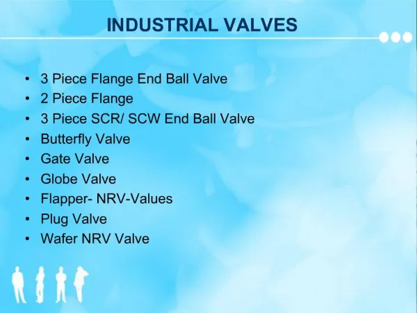
Types of Hydraulic Valves • Directional Control Valve: • Control the direction of flow of the hydraulic fluid to different lines in the circuit • Flow Control Valves: • Control the amount of fluid flow in the circuit • Pressure Control Valves: • Control the pressure in different segments in the circuit B A T P B A P T
B A C F Directional Control Valves T T P B B A P T
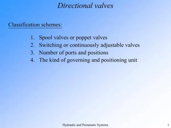
Directional Control Valves • Directional control valves are used to direct inlet flow to a specific outlet ports • They can be classified according to the following: • Internal control element structure • Number of ports or ways • Number of positions • Method(s) of actuation • Center position flow pattern.
Directional Control Valves: Internal Element Structure • The internal control element in directional valves may be a sliding spool, rotary spool, poppet or ball. • The constructional design of the element makes certain classes particularly suitable to specific circuit applications and conditions. of flow. A B P T
Directional Control Valves: Internal Element Structure • The sliding spool valve has a spool fitted inside the valve body. Moving the spool linearly varies the direction of fluid flow. • The spool in the rotary spool valve rotates to change the direction of flow. A B P T
Directional Control Valves: Ways or Ports • The number of ports in a directional control valve is identified by the term way. Thus, for example, a valve with four ports is a four-way valve. • Two-way valves have two working ports. They are used either to open or to close a path for flow in a single line. A check valve is an example on a two-way valve. • A three-way valve has three working ports. It can have one inlet and two outlets or two inlets and one outlet. • Four way valves have four connections to the circuit. The designations P for pressure, T for tank, and A and B for ports on either end of the cylinder are commonly used on four-way valves. Two-Way Valve e.g. check valve Three-Way Valve e.g. Shuttle Valve A B Four-Way Directional Control Valve P T
Directional Control Valves: Positions • The positions in a directional control valve determines the number of alternative flow conditions the valve can provide. • Two-position valves provide two different flow conditions. Open or closed passages from the inlet ports to the outlet ports are changed in each position. • A three-position valve provides three different flow conditions between its ports.
Directional Control Valves:Center Position Flow Patterns • There are several variations in the flow pattern of the center position of a three-way valve. These are made possible by the configuration of the spool. The center configuration affects the circuit behavior when the valve is placed in the center neutral position. • Open center valves allow pump oil to flow through the valve during neutral and return to the tank. Opening the cylinder ports in the center neutral positions causes the cylinder to float. • Closed center valves stop the flow of oil from the pump during neutral. Normally, the cylinder ports are also blocked when a spool is in neutral, which locks the cylinder in position.
Open – Center vs. Closed – Center Systems • In an open – center valve, the pump usually supplies a constant flow of oil, and the oil must have a path for return when it is not required to perform a work. The pressure head on the pump is due to the head losses in the pipe, and is relatively small. • An open – center system is the simplest and least expensive for applications which have only a few functions.
Open – Center vs. Closed – Center Systems • In a closed – center system, the pressure head on the pump becomes large, and the there could be a large waste in power if the pump keeps working at its rated discharge flow rate. • It is usual in closed – center systems to use a variable displacement pump, which adjusts its flow rate according to the pressure head acting on it. This allows the pump to work in a more efficient mode when the valve is at the center position.
Open – Center vs. Closed – Center Systems • Today’s machines need more hydraulic power and the trend has been towards closed – center systems. In a tractor, for example, oil is required to power the steering, the brakes, the hitch, the loader and other equipment. • As more functions are added, with varying demands for each function, the open – center system requires the use of flow dividers to proportion the oil flow to these functions. This reduces the efficiency and results in heat build–up.
Open – Center vs. Closed – Center Systems • There is no requirement for a relief valve in a basic closed – center system employing a variable displacement pump. The pump simply operates in a zero flow rate mode, which prevents heat build-up due to flow through a pressure relief valve. • Closed – center systems employing a variable displacement pump are more efficient, particularly in applications requiring force but little displacement such as power brakes. It allows pump pressure to be constantly applied to brake piston, while the pump is in standby mode.
Directional Control Valves:Method of Actuation • The methods of actuation refer to the various means by which the valve element is moved from one position to another. The different methods available to actuate the valve include • Manual Actuation • Push button • Lever • Pedal • Mechanical Actuation • Spring • Ball and Cam • Fluid (Pilot) • Air (pneumatic) • Oil (hydraulic) • Electromagnetic (solenoid)
Example 1 • For the directional control valve shown, identify the following: • Internal control element • Number of ways • Number of positions • Center position flow pattern • Sketch the symbol of the valve A B P T T
Example 1: Solution • For the directional control valve shown, identify the following: • Internal control element: Spool • Number of ways: 5 • Number of positions: 3 • Center position flow pattern: Closed • Sketch the symbol of the directional control valve shown identifying the flow paths in each envelope A B P T T
Check Valves • The simplest type of a direction control valve. It permits flow in one direction, and prevent any flow in the opposite direction. A check valve is a two-way, two-positions valve. • In a ball type check valve, a light spring holds the ball in the closed position. In the free-flow direction, small fluid pressure overcomes the spring force, and flow is allowed.
No flow direction Free flow direction Check Valves • If flow is attempted in the opposite direction, fluid pressure pushes the ball (along with the spring force) to the closed position. Therefore, no flow is permitted. • The higher the pressure, the greater will be the force pushing the poppet against the seat. Thus increased pressure will not result in any tendency to allow flow in the non-flow direction. • The function and the free-flow directions of the check valve are implied in its symbolic representation.
Pilot Operated Check Valves • A pilot operated check valve always permits free flow in one direction, and permits flow in the normally blocked direction if pilot pressure is applied to the pilot pressure port of the valve. • The dashed line in the symbol represents the pilot pressure line connected to pilot pressure port of the valve.
Pilot Operated Check Valves • In the design shown, the check valve poppet has the pilot piston attached to the threaded poppet stem by a nut. The light spring holds the poppet seated in a no-flow condition by pushing against the pilot piston. • The purpose of the separate drain port is to prevent oil from creating a pressure buildup on the bottom of the piston.
Pilot Operated Check Valves • In the design shown, the check valve poppet has the pilot piston attached to the threaded poppet stem by a nut. The light spring holds the poppet seated in a no-flow condition by pushing against the pilot piston. • The purpose of the separate drain port is to prevent oil from creating a pressure buildup on the bottom of the piston.
Example 2 • The figure shows a preliminary setup for a hydraulic system utilizing a double acting cylinder for moving a bidirectional load. • From a safety point of view, what problem does this system have? What happens in case of hydraulic line rupture, pump failure, or electrical power shutdown in the position shown? • Propose a design update using pilot operated check valves to lock the cylinder in position in case of power failure. Fload
Fload Proposed Solution 1: Regular check valves • Utilizing ordinary check valve would lock the cylinder permanently, disallowing its motion regardless of pump pressure.
Fload Proposed Solution 2: Pilot check valves • Utilizing pilot check valve would lock the cylinder when failure occurs. When there is enough pump pressure (a sign of normal healthy conditions), the cylinder can be extended or retracted normally.
Pressure Control Valves • Pressure control valves protect the system against overpressure, which may occur due to gradual buildup as fluid demand decreases, or due to sudden surge as valves open or close. • In hydraulic systems, pressure surges can produce an instantaneous increase in pressure as much as four times the normal system pressure. Shock absorbers are hydraulic devices designed to smooth out pressure surges and to dampen hydraulic shock.
Pressure Control Valves • The gradual buildup of pressure can be controlled by a pressure compensated pumps. Additionally, the following valve types are used to control fluid pressure: • Direct Acting Pressure relief valves • Compound Pressure relief valves • Unloading valves • Sequence valves • Counterbalance valves • Pressure reducing valves
P T Direct Pressure Relief Valves • The most widely used type of pressure control valve is the direct pressure relief valve. It is found practically in every fluid power system. • The direct pressure relief valve is a normally closed valve whose function is to limit pressure to a specified maximum by diverting pump flow back to the tank. • In a simple pressure relief valve a ball or a poppet is held seated inside the valve by a heavy spring. When the system pressure reaches a high enough, the ball is force off its seat. This permits flow through the outlet to the tank as long as this high pressure is maintained. P T A
Direct Pressure Relief Valves • The pressure relief valve provides protection against overload experienced by the actuators in a hydraulic system. One important function is to limit the force or torque produced by the hydraulic cylinders or motors.
P T Direct Pressure Relief Valves • Most pressure relief valves are adjustable. By turning a screw installed behind the spring in or out, the relief valve can be adjusted to open at a certain pressure. The pressure at which the valve begins to open is called the cracking pressure. • The pressure when the valve opens enough to allow full pump flow can be substantially greater than the cracking pressure. The pressure at full pump flow is the pressure level that is specified when referring to the pressure setting of the relief valve. It is the maximum pressure permitted by the relief valve, and should be set around the maximum working pressure of the system.
Example 3 • A pressure relief valve with a poppet area of 650 mm2 and a spring constant of 450 kN/m has its spring is initially compressed by 5 mm. The poppet must move by 2.5 mm from its fully closed position in order to pass full pump flow through the valve. • Determine the cracking pressure of the valve. • Determine the pressure of the valve needed for full pump flow through the valve P T A
Example 3 Solution • A pressure relief valve with a poppet area of 650 mm2 and a spring constant of 450 kN/m has its spring is initially compressed by 5 mm. The poppet must move by 2.5 mm from its fully closed position in order to pass full pump flow through the valve. • At cracking pressure, fluid force balances initial spring compression. • At full pump flow pressure, fluid force balances the total spring compression. P T A • The full pump flow pressure is 50% higher than the cracking pressure
Compound (Pilot) Pressure Relief Valves • The pressure override caused by the spring in a direct acting relief valve may result in a considerable power loss owing to the fluid being lost unnecessarily at a pressure between the cracking pressure and the full opening pressure. • This happens when the inlet area of the valve is enlarged to accommodate high flow rates. A large inlet area calls for a stronger spring to balance fluid forces when the valve is closed, which, in turn, leads to high spring force when the spring deflects, and a large pressure override. P T A
Compound (Pilot) Pressure Relief Valves • A compound pressure relief valve uses the flow medium itself to apply the closing force on the valve disc through a pilot supply line assembly. • The exposed bottom area of the disc is less than the top area. As both ends are exposed to the same pressure, the closing force, resulting from the larger top area, is greater than the inlet force. The resultant downward force therefore holds the piston firmly on its seat.
Compound (Pilot) Pressure Relief Valves • A pilot valve, which is itself a small direct pressure relief valve is used to sense the fluid pressure. when the inlet pressure reaches the set pressure, the pilot valve will pop open, releasing the fluid pressure above the disc. • With much less fluid pressure acting on the upper surface of the piston, the inlet pressure generates a net upwards force and the piston will leave its seat. This causes the disc to pop open quickly with little pressure override, diverting the full flow of the pump to the tank.
Compound (Pilot) Pressure Relief Valves • When the inlet pressure has been sufficiently reduced, the pilot valve will reclose, preventing the further release of fluid from the top of the piston, thereby re-establishing the net downward force, and causing the piston to reseat.
Example 4: Power loss in Pressure Relief Valves • A pressure relief valve has a pressure setting of 7000 kPa. Calculate the power loss in the valve if it admits a full pump flow of 1.26 x 10 -3 m3/s.
Example 4: Power loss in Pressure Relief Valves • A pressure relief valve has a pressure setting of 7000 kPa. Calculate the power loss in the valve if it admits a full pump flow of 1.26 x 10 -3 m3/s.
Unloading Valves • An unloading valve is a pressure control valve that operates in a manner somewhat similar to a pilot pressure relief valve. • In contrast to a piloted pressure relief valve, which responds to pressure in the circuit just upstream the valve, an unloading valve responds to a pilot pressure coming from a remote source.
Unloading Valves • An unloading valve permits a pump to build pressure to an adjustable pressure setting, and then allows it to discharge to the tank at essentially zero pressure as long as pilot pressure is maintained from the remote source. • With the unloading valve, the pump has essentially no load and is developing a minimum amount of power. With a pressure relief valve, the pump is delivering full pump flow at the pressure relief valve setting, and is thus operating at maximum power conditions.
Unloading Valves • Note that the chamber containing the spring is ported to the discharge side of the valve which will be normally be connected to the tank. This is necessary so that the small leakage past the spool into this chamber due to inlet pressure will not build up in the spring chamber, and hence prevent the valve from opening. • This valve is said to be internally drained because the path from the spring chamber to the discharge side of the valve lies inside the valve itself. Note the symbol for the unloading valve. P A T