Download
1 / 49
490 likes | 688 Views
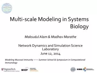
Modeling & Simulation of Glass Structure VCG Lecture 20. John Kieffer Department of Materials Science and Engineering University of Michigan. Overview …. Historical perspective Simulation methodologies Theoretical background Monte Carlo simulation Molecular dynamics simulation

E N D
Modeling & Simulation of Glass StructureVCG Lecture 20 John Kieffer Department of Materials Science and Engineering University of Michigan
Overview … • Historical perspective • Simulation methodologies • Theoretical background • Monte Carlo simulation • Molecular dynamics simulation • Reverse Monte Carlo • Force fields • Information retrieval • Statistical mechanical formalisms • Structural analyses • Dynamics • Application examples
Implementing Metropolis MC A MC simulation of a material is easy to perform. • At each iteration of the simulation, a new configuration is generated. This is usually done by making a random change to the coordinates of a single randomly chosen particle using a random number generator (RNG). E.g. xnew = xold + h1drmax ynew = yold + h2drmax znew = zold + h3drmax Here h = 2x-1 and x is in the range (0,1). Drmax is the maximum allowed displacement in any direction. • A unique random number is generated for each direction.
Implementing Metropolis MC • The potential energy of the new configuration is then calculated. • Since the change from the previous configuration involves the motion of a single particle, only those contributions to the energy resulting from the particle’s new position need to be recalculated. • If periodic boundaries are used, the minimum image convention must be invoked in calculating the energy (more on this later).
Implementing Metropolis MC • If the new configuration is lower in energy than the previous configuration, then the new configuration is retained as the starting point for the next iteration. • If not, then the Boltzmann factor exp(-[Unew-Uold]/kBT) is calculated and compared to a random number between 0 and 1. • If the random number is less than or equal to the Boltzmann factor, the new configuration is accepted. • If the random number is greater than the Boltzmann factor, the new configuration is rejected and the previous configuration is retained for the next iteration. The acceptance criterion can be written as: rand(0,1) ≤ exp(-DU(rN)/kBT) reject accept
Detailed Balance • The acceptance criterion in Metropolis Monte Carlo is derived by imposing the condition of detailed balance • It assures unique limiting probability distribution N possible states Probability that state i is occupied: i = Z-1·exp[–Ui/kBT] Probability distribution of states = (1, 2, 3, …, n, …, m, …, N) Transition matrix : mn = probability that system transitions from state m to n Stochastic matrix : mn = probability that algorithm seeks transition from state m to n P(E) E
Detailed Balance In the Metropolis algorithm:
Detailed Balance Example: 2-level system; state 1 twice as likely as state 2
Detailed Balance Assume = (1, 2) = (1,0)
Metropolis MC: Markov Chains • The Metropolis algorithm generates a Markov chain of states of the system. • A Markov chain satisfies the following two conditions: • The outcome of each trial depends only upon the preceding trial and not on any other previous trials. • Each trial belongs to a finite set of possible outcomes. • The first condition distinguishes the MC method from the MD method: in an MD simulation, all states are connected deterministically in time.
Detailed Balance • Why accept any moves that raise the energy? • Consider the alternative: any move that lowers the energy is accepted, any move that raises the energy is rejected. The consequence of this is that thermal fluctuations would not be allowed, and phase space would not be properly explored at the given temperature. • This would be equivalent to simulating at zero temperature. • In any system in equilibrium at temperature T, thermal fluctuations occur that occasionally raise the energy. These fluctuations allow the system to explore phase space and allow all atoms to experience all environments.
Implementing Metropolis MC Choosing the size of the displacement: • At each iteration, the size of the move is governed by the maximum displacement drmax. • The max displacement drmax is an adjustable parameter whose value is usually chosen so that 50% of the trial moves are accepted. • If drmax is too small, then many moves will be accepted but the states generated will be very similar to the previous ones and the system will explore phase space very slowly. • If drmax is too large, then very few moves will be accepted because they lead to unfavorable overlaps. • drmax can be adjusted automatically while the program is running to achieve the desired acceptance ratio by keeping a running score of the proportion of moves that are accepted.
Example:MC Simulation of a Binary Mixture • Example: A binary mixture of two species with interaction energies eAA, eBB, and eAB and identical molecular size s. The values of e characterize the well depths of the van der Waals interactions between any two molecules. • To simplify, discretize space and allow the molecules to move only by discrete amounts. That is, allow the molecules to move on the sites of a lattice. Example: eAA = -0.5 eBB = -0.5 eAB = -1 e = eAB–(eAA+ eBB)/2 Tc = 2.27 Energy of mixing fA
MC Simulation of a Binary Mixture • Choose a particle at random (pink square). • Choose a neighboring particle at random (green square). • This defines the MC “move” - we will attempt to swap these two particles. • Calculate the current and new potential energy of the two particles. Old New
MC Simulation of a Binary Mixture • If DE < 0, accept the move. If not, calculate Boltzmann factor and compare with a random number. Accept if rand(0,1) ≤ exp(-DE/kBT). • Note bounds: If T very large, then BF close to one, and move nearly always accepted. If T very small, then BF is very small, and move is rarely accepted. Old New
Overview … • Historical perspective • Simulation methodologies • Theoretical background • Monte Carlo simulation • Molecular dynamics simulation • Reverse Monte Carlo • Force fields • Information retrieval • Statistical mechanical formalisms • Structural analyses • Dynamics • Application examples
Reverse Monte Carlo Method introduced by Robert McGreevy† Reverse MC MC Structural Characteristics (e.g., S(Q)) Interaction Energy Equilibrium Configuration compare Experiment † R.L. McGreevy and L. Pusztai, Mol. Sim. 1, 359 (1988); R.L. McGreevy, J. Phys. Cond. Matter 13, R887 (2001)
Reverse Monte Carlo • Create “reasonable” starting configuration • evaluate S(Q)
Reverse Monte Carlo • Move one particle and re-evaluate S(Q) • Only contribution of the one particle that moved needs to be considered
Reverse Monte Carlo • Compare simulated S(Q) with experimental one • Evaluate agreement factor c2
Reverse Monte Carlo • Calculate ∆c2 = c2 (after move) – c2 (before move) • If ∆c2 ≤ 0, accept move • If ∆c2 > 0, compare to random number and move accept if • Otherwise reject move
Reverse Monte Carlo • Method maximizes entropy, i.e. strives towards most disordered structure that produces given S(Q) • Must use maximum range of experimental S(Q) • Impose additional constraints (e.g., coordination number, bond angles, etc.) • Combine with MD
Overview … • Historical perspective • Simulation methodologies • Theoretical background • Monte Carlo simulation • Molecular dynamics simulation • Reverse Monte Carlo • Force fields • Information retrieval • Statistical mechanical formalisms • Structural analyses • Dynamics • Application examples
Equations of motion … Recall the Lagrangian
Solving the equations of motion … 6N 1st-order equations 3N 2nd-order equations
Molecular Dynamics Simulations Compute force on each particle interactions based appropriate interaction model Iterate every 0.002 ps Compute displacement of particles in a short time interval based on accelerations Update positions
Molecular Dynamics Simulation • Basic MD simulation program: • Read in run parameters (e.g. initial energy or temperature; N) • Initialize positions and velocities • Compute forces on all particles • Integrate Newton’s equations (F = ma) • Update particle positions and velocities • Calculate instantaneous properties • Stop after iterating tmax steps repeat
MD: Four basic parts Initialization • Setting up initial conditions. • Boundary conditions. Force Calculation • Dealing with different kinds of forces. • Tricks tracking particles. Integration Updating of xi,vi • Different integration schemes. • Different thermodynamic ensembles. Recording of data Calculation of properties • What to calculate? • Averaging data
MD Simulation: Integration Schemes • There are many finite difference algorithms, and several are commonly used in MD simulations (many are related). • Each has trade-offs: • accuracy • stability • time reversibility • area preserving • memory requirements • complexity • Many research papers just on algorithm design for solving F = ma.
MD Simulation: Integration Schemes • All algorithms start from assumption that the positions, velocities, and accelerations can be approximated by a Taylor series expansion: where etc.
MD Simulation: Euler • The Euler algorithm uses the positions, velocities and accelerations at time t to calculate the new positions r(t+dt): • Simplest integration scheme. • Bad: Not very accurate, so suffers from catastrophic energy drift. Not area preserving or time reversible. • NOT RECOMMENDED; never used. • Problem: uses only values at one time to estimate new values. All algorithms in use today “interpolate”.
MD Simulation: Verlet • The Verlet algorithm uses the positions and accelerations at time t, and the positions from the previous step r(t-dt), to calculate the new positions r(t+dt): • The velocities do not appear in the Verlet integration scheme: velocities are not necessary for generating particle trajectories. +
MD Simulation: Verlet • To obtain the new velocities, we can calculate them from the difference between the positions at two different times: or
MD Simulation: Verlet • Advantages: • Implementation is straightforward. • Storage requirements are modest: • two sets of positions and one set of accelerations. • 9N stored numbers • Disadvantages: • Positions are calculated by adding a small term of order dt2 to the difference of two much larger terms, which may lead to a loss in precision: • Velocities always lag behind positions. • Poor stability for large dt.
MD Simulation: Leap-Frog Hockney1970 • Several variations on the Verlet algorithm have been developed, including the leap-frog algorithm: • The velocities at time t can be calculated from: • The velocities leap-frog over the positions to give their values at t+dt/2. The positions then leapfrog over the velocities to give their new values at t+dt, then the velocities at t +3dt/2, and so on.
MD Simulation: Leap-Frog • Advantages over standard Verlet: • Explicitly includes velocity (needed for kinetic energy). • Does not require calculation of differences of large numbers, so more accurate. • Same memory requirements (9N) as Verlet. • Disadvantages over standard Verlet: • Positions and velocities are not synchronized. • Cannot calculate kinetic energy (from velocities) and potential energy (from positions) at the same time. • Not a problem - can always estimate v(t) from v(t+dt/2) and v(t-dt/2) if you need it. Almost always used over Verlet.
MD Simulation: Velocity Verlet Swope, et al1982 • The velocity Verlet method gives positions, velocities, and accelerations at the same time without compromising precision: • Implemented in three stages since calculating velocities requires accelerations at both t and t+dt. Looks like Euler from position eqn, but isn’t!
MD Simulation: Velocity Verlet Swope, et al1982 • Actual implementation trick: • Velocities at t+1/2dt are calculated using information at t. • With these terms in memory, calculate: • Calculate ai(t+dt) from forces using positions at t+dt, and from this and vi(t+dt/2), calculate vi(t+dt).
MD Simulation: Other Integration Schemes • The “order” of an integration method is the degree to which the Taylor series expansion is truncated -- it is the lowest term not present in the expansion. Sometimes this is not obvious. • Verlet is a 4th order method since 3rd order terms (not shown) cancel when expressions are added, which means positions are accurate to order dt4. But, velocities only accurate to dt2. • Velocity verlet also accurate to 4th order in positions, 2nd order in velocities. • Velocity-corrected Verlet is 4th order in positions and velocities. • Predictor-corrector methods [Gear 1971] form a general family of integration algorithms from which one can select a scheme that is correct to any given order. - But, not area preserving and not time-reversible.
MD Simulation: Predictor-Corrector Methods Three basic steps: • Values of r(t+dt), v(t+dt), a(t+dt) and higher order terms predicted from Taylor expansion using values at time t only:
MD Simulation: Predictor-Corrector Methods Three basic steps: 2. Forces are calculated at r(t+dt) to give a second estimate for aF(t+dt). These values of acceleration are compared with those predicted from Taylor series expansion, a(t+dt). 3. The difference between the predicted and calculated accelerations is then used to correct the positions, velocities, etc. in the correction step:
MD Simulation: Predictor-Corrector Methods Corrected values: • Gear has suggested “best” values of the coefficients c0, c1, … . Which set of “magic numbers” to use depends on the desired order of the algorithm. Here the expansion has been truncated after the third derivative of the positions (4th order), and one uses c0 = 1/6, c1 = 5/6, c2 = 1, and c3 = 1/3.
MD Simulation: Comparing Integration Schemes • Compare Predictor-Corrector vs. Verlet: • Memory req’d for Gear is (O+1)x3N, where O = order of highest derivative in Taylor series expansion, 1 is for extra acceleration, 3N = # particle coordinates. Present example: 15N. • Memory req’d for Verlet is 3 terms x 3N coords = 9N. • Gear requires two force evaluations per time step, but may permit a dt that is more than twice as long.
MD Simulation: Comparing Integration Schemes • Which algorithm is “best”? • Fast • Require minimal memory • Easy to program • Time reversible - not always needed. • Area preserving - not always needed. • Accurate: conserve energy and momentum • NVE - total energy is constant, except for accuracy of algorithm (and machine precision - only matters for forces). • A variation of one part in 104 is acceptable for most applications. • Different algorithms vary in rate at which error varies with time step • E.g. Predictor-corrector accurate for short time steps, Verlet more accurate for larger time steps. • Stable for large dt Most meet this requirementon today’s computers. Verlet Gear P.-C.
MD Simulation: Choosing the Time Step • Want as large a dt as needed to generate a trajectory over time scales sufficient for problem. • Time step dt can’t be too large or integration algorithm will be inaccurate and could be unstable. • If step too large, force will change too much: this causes inaccuracy. • If forces become too large (i.e. particles move too close together in a single time step, this causes instability.) dtsmaller dtlarger
MD Simulation: Choosing the Time Step • Time step dt must be smaller than the smallest time relevant to oscillatory motion. • Atomic systems: dt << toscillation (typically dt = 2 fs) • Molecular systems: dt < 0.1tshortest osc. period • Usually the highest frequency vibrations are due to bond stretches, especially due to bonds to H atoms, and tshortest = tbond stretch. (tC-H 10 fs so dt = 1 fs)