Download
1 / 15
150 likes | 296 Views
Lonny Berman EFAC May 10 th 2007. ID Beamline Optics and Damping Wigglers. Outline. Hard x-ray undulator beamline monochromator thermal modelling (silicon and diamond) Hard x-ray undulator beamline mirror modelling Damping wiggler beamline monochromator thermal modelling (silicon)

E N D
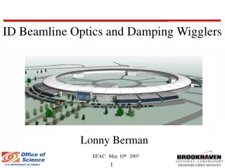
Lonny BermanEFACMay 10th 2007 ID Beamline Optics and Damping Wigglers
Outline Hard x-ray undulator beamline monochromator thermal modelling (silicon and diamond) Hard x-ray undulator beamline mirror modelling Damping wiggler beamline monochromator thermal modelling (silicon) Damping wigglers: to cant or not to cant
Undulator Beamline Silicon Monochromator Simulation of “hockey-puck” liquid nitrogen cooled crystal design using 2σ beam size (1.2 mm wide x 0.75 mm high) from U14 superconducting undulator at maximum K, 30 m distance from source, 12.7º Bragg angle (corresponds to 8.9 keV for Si(111)). Total power = 109 W (unfiltered), 92 W (filtered) Maximum temperature = 98 K (unfiltered), 94 K (filtered) Maximum thermal slope error in beam footprint = ±5 µrad (unfiltered), ±4 µrad (filtered) Courtesy of Viswanath Ravindranath
4 m Long Undulator Case with Filter Conclusion: for silicon, there is no better temperature for the illuminated area of the crystal to be at, than 125 K. Action Item: investigate the use of controls and diagnostics to make sure that this is the temperature of the illuminated area of the crystal.
Using a Water-Cooled Diamond The diamond wafer is 0.5 mm thick and the (111) Bragg reflection is used (Bragg angle is 19.7º at 8.9 keV). Beam size 2.4 mm wide x 1.5 mm high (4σ). Here, 60% of the incident power is transmitted through the crystal, and the depth dependence of the 40% absorbed power has to be taken into consideration. The transmitted power propagates through a hole in the copper substrate. There is 1 mm of overlap of the diamond wafer and copper substrate all around. A crucial consideration, in such a design, is the thermal contact between the diamond and the substrate. Courtesy of Paul Montanez
Diamond Crystal Peformance Conclusion: pathways to improvement involve better thermal contact, larger contact area, thinner diamond to absorb less power. Action Item: watch developments in the field, as the main challenge with diamonds is in obtaining an assured supply of large, good quality crystals.
NSLS X25 1 m Long Vertical Focusing Mirror demag. source,σ’ ellipse electron source size, σ VFM 1 m long dynamically bent palladium coated mirror, fused silica substrate. X25 Mirror Bender System X25 Vertical Mirror Parameters Source to Optic = 23 m Optic to Focus = 3.5 m Demag = 6.6:1 measured rms slope = 1.4 μrad NSLS-I perfect image size fwhm = 3.25 μm calc. image size incl. fig. err. fwhm = 23 μm NSLS-II perfect image size fwhm = 1.1 μm calc. image size incl. fig. err. fwhm = 23 μm 3.5 m 23 m Courtesy of James Ablett
X25 SHADOW Ray-Tracing X25 Mirror at NSLS-I X25 Mirror, fwhm = 16.6 μmIdeal Mirror, fwhm = 3.2 μm vertical [microns] X25 Mirror rms slope=1.4 μrad y [μm] Ideal Mirror distance along mirror [cm] Source X25 Mirror at NSLS-II x [mm] Normalized Intensity X25 Mirror at NSLS-II X25 Mirror, ‘width’ ~ 16 μmIdeal Mirror, fwhm = 1.03 μm vertical [microns] X25 Mirror y [μm] distance along mirror [cm] Ideal Mirror Source x [mm] Normalized Intensity
Damping Wiggler Silicon Monochromator We looked at the same crystal design as we used for undulator beams, and studied its performance using different size wiggler beams. The case shown here is based on a beam size of 3.6 mm wide x 2.25 mm high at 30 m from the 7 m long damping wiggler source (original design), Si(111) at 8.9 keV (Bragg angle 12.7º). Total power = 475 W Maximum temperature = 125 K Maximum thermal slope error in beam footprint = ±6.6 µrad, not bad! Courtesy of Viswanath Ravindranath
Damping Wiggler Mono Using Bigger Beam We also looked at the case of a beam size twice as large in the horizontal and vertical directions, i.e. 7.2 mm wide x 4.5 mm high. Total power = 1.77 kW Maximum temperature = 355 K Maximum thermal slope error in beam footprint = ±300 µrad Notice that the temperature rise in this case is no longer concentrated right at the beam footprint. The crystal is too small in size to handle the power. Conclusion: bigger beams require bigger crystals with bigger cooling interfaces. Courtesy of Viswanath Ravindranath
Damping Wigglers: To Cant or Not to Cant • Multiple yet independent damping wiggler beamlines may be accommodated in individual straight sections, either by viewing different off-axis portions of the same damping wiggler fan, or by viewing on-axis radiation emissions from separate wigglers which are canted by a few milliradians with respect to each other. • The larger the canting angle, the larger the impact on the emittance of the ring. E.g. if two 3.5 m long wigglers canted by 2 mrad with respect to each other are installed in each of these 8 straight sections, then the emittance increases by 8%. Critical Energy Dependence Across Each Canted Wiggler Radiation Fan For each fan: Ec = Ec,max(1-[ө/өmax]2)1/2 өmax = K/γ Ec (keV) 2 mrad 10.8 keV 10 5 0 -5 5 0 ө (mrad)
Flux Variation Across Wiggler Fan Courtesy of Steve Hulbert Flux Conclusion: canted damping wigglers offer no advantages for flux-dependent applications except at the highest photon energies, as compared with viewing the fan at even 1.5 mrad off-axis horizontally.
Brightness is a Different Matter Brightness Conclusion: when viewed at 1 mrad off-axis horizontally, the horizontal source size of a 7 m long damping wiggler will appear to be 7 mm wide, diminishing the brightness by a factor of ~20, relative to on-axis viewing. Insertion device codes do not handle this effect correctly, but it has been empirically observed at the X25 wiggler: Lonny Berman and Zhijian Yin (1997) If brightness is an important consideration for a damping wiggler source, it must be viewed on-axis. The only means to achieve this, for two completely independent beamlines, is to implement canted damping wigglers.
Conclusions Existing liquid nitrogen cooled silicon crystal design will handle NSLS-II undulator beams, with attention to temperature control For water-cooled diamond crystals to be effective in NSLS-II undulator beams, attention to crystal size and thermal contact is necessary Small mirror figure errors can introduce structure into an NSLS-II undulator focused beam as well as blur image Liquid nitrogen cooled silicon crystal designed for an NSLS-II undulator beam could handle a damping wiggler beam with dimensions of ~4-5 mm; larger size beams will need to be handled by larger size crystals Canted damping wigglers pose no advantage for flux-dependent applications (compared with off-axis views of a single wiggler), but will be necessary for brightness-dependent applications if more than one independent beamline per damping wiggler straight section is desired