1 / 27

Test results of MKD/B1 UA63/67 radiation levels

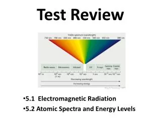
Test results of MKD/B1 UA63/67 radiation levels. Viliam Senaj LIBD meeting 25/09/2013. Radiation measurements in UA63/67. Schematics of UA63. Schematics of UA67. Evaluation of TLDs installed in 2009. To be learned from the radiation measurements.

arich
Download Presentation

Test results of MKD/B1 UA63/67 radiation levels

An Image/Link below is provided (as is) to download presentation Download Policy: Content on the Website is provided to you AS IS for your information and personal use and may not be sold / licensed / shared on other websites without getting consent from its author. Content is provided to you AS IS for your information and personal use only. Download presentation by click this link. While downloading, if for some reason you are not able to download a presentation, the publisher may have deleted the file from their server. During download, if you can't get a presentation, the file might be deleted by the publisher.

E N D

Presentation Transcript


  1. Test results of MKD/B1 UA63/67 radiation levels ViliamSenaj LIBD meeting 25/09/2013

  2. Radiation measurements in UA63/67

  3. Schematics of UA63

  4. Schematics of UA67

  5. Evaluation of TLDs installed in 2009

  6. To be learned from the radiation measurements • Radmons - too insensitive (for doses at UA) • TLDs – clear effect of non-shielded ducts (in front of Gen. G/H & N/O) • Visible effect of shielded duct in front of Gen.C – no increased dose • To evaluate TLDs correctly we need to deduce background (x-ray etc.) but we don't have reference measurement. Background estimated to 0.8 mSv. HEH = dose x 2.5e6 so max HEH fluences ~ 6e5 HEH/cm2 (if neglected 2009-2011) • Average fluence probably close to estimated one (1e5 HEH/cm2.year) • Shielding of residual large openings requested

  7. T_delay comparison prior and after LS1 maintenance

  8. T_rise comparison prior and after LS1 maintenance

  9. I_ref100% comparison prior and after LS1 maintenance

  10. R_end comparison prior and after LS1 maintenance

  11. R_1 comparison prior and after LS1 maintenance

  12. R_2 comparison prior and after LS1 maintenance

  13. Corrected T_delay after LS1 maintenance

  14. T_riseafter LS1 maintenance

  15. Target T_delay after LS1

  16. I_ref/E after LS1 maintenance

  17. T_rise after LS1 maintenance

  18. R1 after LS1 maintenance

  19. New settings

  20. Comparison MKBs – I_max1

  21. Comparison MKBs – I_min1

  22. Comparison MKBs – R_max2

  23. Comparison MKBs – T_zero1

  24. Comparison MKBs – T_zero4

  25. Comparison MKBs – Low_thr

  26. Resonance between GTO stacks without and with damping ferrite tores • Artificially induced resonant ringing between 2 stacks (1 nf in parallel with 1 GTO) – simulating effect of sparking; signal measured on retring pick-ups Cts2 a&b • Resonance at ~ 2 MHz with low damping factor generally observed • Adding of a lossy ferrite in HV path of each GTO stack (tore cutted in two – no need for dissasembly) – reducing resonant frequency to ~ 1 MHz; significant damping and saturation effect (increasing T_threshold and reducing T_rise)

  27. Energy scan without and with FT Increased T_thr without much influence to T_delay = reduced T_rise (~-30 ns)

More Related