Download
1 / 18
180 likes | 279 Views
EEF Contribution to the Business submission Tony Clohesy, Pera. Submission: work completed on the SMED prototype (Single Minute Exchange of Die). My placement Pera Innovation, Melton Mowbray.

E N D
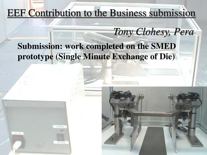
EEF Contribution to the Business submission Tony Clohesy, Pera Submission: work completed on the SMED prototype (Single Minute Exchange of Die)
My placement Pera Innovation, Melton Mowbray I have been at Pera since August, and have done work on a number of projects such as the one shown, WREED, an airless dryer for food which uses superheated steam. I did a lot of work on a temperature control system for a medical supplies box, MEDICASE. I have also conducted a number of tests on various types and constructions of insulation to increase the efficiency of home delivery – E-FLEX The project my submission focuses on is SMED, a short-term prototype building project where I was heavily involved in all aspects of the project from design and construction to testing and documentation.
The Task SMED prototype Develop a method of improving the efficiency of food processing Specifically shortening changeover time for manually adjusted equipment Demonstrate the concept on a box folding machine Provide a fully computer controlled demonstration prototype for display at relevant conferences
Overview of the project • A copy of the box folding machine from a large-scale bakery had been produced and fitted with linear actuators. • Motor control circuits were used to regulate the positioning of the various parts.
Linear Actuators • There are four actuators, two controlling the distance between the guiding plates and two controlling auxiliary arms behind the guiding plates. • They are connected via the motor control circuit to a 12V supply, and also have a 5V current across the potentiometer to allow position information to be read back from it.
Micro-controller • The micro-controller is mounted on a demonstration board which has additional features such as a programming port, serial communications port and banks of inputs and outputs including a 5V supply used by other circuits. • Outputs include the 5V supply to the motor potentiometer and motor control signals to the relevant circuit.
Motor Control Circuit • I designed and built this circuit around a chip containing a commonly used circuit known as the H-bridge. • The H-bridge accepts logic signals from the micro-controller and channels a useable supply to the motor. Depending on the inputs, the chip makes the actuators move in or out.
Buffer Circuit • Operational amplifiers in this context are used to ensure the voltage being read is not distorted by internal resistances. The positioning of the actuators is crucial, and this circuit was added after preliminary testing to ensure accurate readings from the potentiometer feedback. • I designed and built this circuit on strip-board and it intercepts the feedback wire from the potentiometers to the micro-controller.
Regulator Circuit • This circuit was built using linear regulators for the purpose of protecting the delicate components of the control circuits by means of current limiting capabilities. • Variable resistors are used with the linear regulator chips to control the voltage to the actuators and hence the speed.
Main challenges (1) • Basic method worked, but a few hitches were uncovered in initial tests: • High current draw burnt out H-bridge chips in the motor control circuit • Inaccurate measuring of position • Fast movement caused overshoot of target position. • Slow recognition of target position by interrupt sequence
Main challenges (2) • High current draw: • Initial movement of the actuators required a higher than nominal current, and when all four moved at once this current was sufficient to overheat the H-bridge chips in the motor control circuit. • Different sized resistors were used to reduce the voltage during testing, but then the power supply was changed and the regulator circuit introduced.
Main challenges (3) • Inaccurate position measurement: • The position was measured by the potentiometer, but internal resistance meant that the values entering the micro-controller were not reliable. • The addition of the buffer circuit meant that the correct voltages could be read with no adverse effects from other resistances.
Main challenges (4) • Fast movement caused overshoot of target: • A ‘hard stop’ option is available where the motor is stopped dead instead of slowing to a stop. This draws a lot of power, but is more accurate. We decided not to use this, but to run the motors slower and to increase the frequency of potentiometer readings by the micro-controller.
Main challenges (5) • Slow target recognition: • The sequence in the code which runs every few milliseconds performs the actions required by the serial cable communications, and checks the position at every cycle. • This was not checking fast enough to give high-resolution feedback during motion, so the code was changed to increase cycle time.
Extra work • All circuits were mounted in an aluminium box. • Mains power socket with lights and switches mounted in side. • Connectors from the box to the actuators to allow disconnection during transit were wired up and mounted. • All relevant datasheets and technical information was gathered for the main components used. • Circuit diagrams and design drawings were produced for all parts of the prototype. It is our intention to ensure the prototype is suitable for CE marking. • Records of purchases and man-hours spent have been kept up-to-date.
Impact of project (1) • It is too early to assess the impact in real terms as yet, but there a number of factors to consider: • Pera retains a valuable client • Prototype displayed for potential investors to see • The changeover time of this particular piece of equipment has been identified as the main Limiting Factor of the production line, and has the potential to save a lot of monetary and labour costs associated with flexibility of production.
Impact of project (2) • Increasingly, the food industry is seeing the necessity for rapid changeover as batch sizes get smaller and flexibility is crucial for success. • When manual changeover of equipment such as the box folder takes up to 10 or 15 minutes to complete, with all the added safety risks involved, it is not financially viable to change the settings for batches which alter every hour. • For a £15,000pw output, every minute is valuable, and if you are changing batches hourly, every week: • Manual changeover would waste 400 minutes and £2500 • SMED changeover would waste only 40 minutes and £250 • - a saving of 6 hours of skilled labour and £2250
Conclusion • My personal development: • Teamwork skills, Communication • Manual skills, Electrical knowledge • Problem solving, Organisation • The prototype: • The SMED concept has been realised with a working display model which can be easily transported and set up using only a standard mains plug and a laptop. The combination of computer program, micro-controller program and circuitry presents a robust user interface ideal for exhibitions and potential new clients.