Download
1 / 2
20 likes | 154 Views
R 1. _. LT1124. MC1741. TrimPot 10 k Ω. R 2. +. Output B. R 1. R 3. R 2. R 4. Main Amp. Output A. Output. LT1124. EMG ANALYSIS CIRCUIT. Electrode Preamplification Differential Measurement. Belt-mounted unit. Main amplifier Filtering Amplification.

E N D
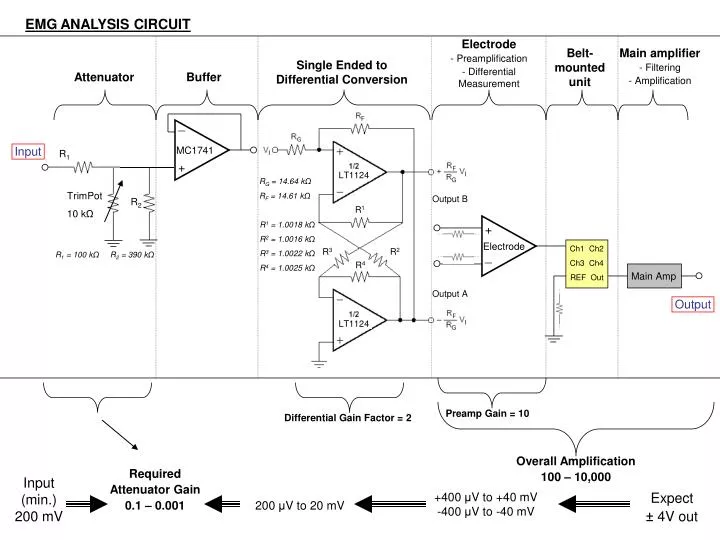
R1 _ LT1124 MC1741 TrimPot 10 kΩ R2 + Output B R1 R3 R2 R4 Main Amp Output A Output LT1124 EMG ANALYSIS CIRCUIT • Electrode • Preamplification • Differential Measurement Belt-mounted unit • Main amplifier • Filtering • Amplification Single Ended to Differential Conversion Attenuator Buffer Input RG = 14.64 kΩ RF = 14.61 kΩ R1 = 1.0018 kΩ R2 = 1.0016 kΩ R3 = 1.0022 kΩ R4 = 1.0025 kΩ + Electrode Ch1 Ch2 Ch3 Ch4 REF Out R1 = 100 kΩ R2 = 390 kΩ _ Preamp Gain = 10 Differential Gain Factor = 2 Overall Amplification 100 – 10,000 Required Attenuator Gain 0.1 – 0.001 Input (min.) 200 mV Expect ± 4V out +400 μV to +40 mV -400 μV to -40 mV 200 μV to 20 mV
RT Attenuator R1 Vi Vo Then, where α is the gain of the attenuator. where RT is the parallel combination of R2 & the Trim potentiometer (TP) When R2 >> RT, then TP ~ RT Since α must range from 0.1 – 0.001, then based on a chosen R1 = 100 kΩ, RT must range from 11 kΩ to 100 Ω Choosing R2 = 390 kΩ, results in TP = 11 kΩto 100 Ω