Download
1 / 17
170 likes | 341 Views
Atomic beam studies in the H-jet polarimeter. A.Zelenski. PSTP2007, September 11,BNL. H - jet polarimeter. Dissociator. Compression tube calibration. Ø - 10 mm. H 0. Hydrogen mass-flow controller MKS. Full range: 0.0-1.0 scc/min. Absolute accuracy 1-2%.

E N D
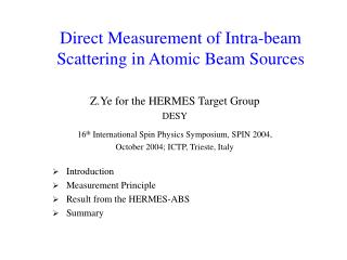
Atomic beam studies in the H-jet polarimeter. A.Zelenski PSTP2007, September 11,BNL
H - jet polarimeter. Dissociator
Compression tube calibration. Ø -10 mm. H0 • Hydrogen mass-flow controller MKS. Full range: 0.0-1.0 scc/min. Absolute accuracy 1-2%. • Conventional technique: pressure drop in calibrated volume. • Independent AB intensity measurement from the well known TMP pumping speed. Length-10 cm H2 Hot filament ion gage.
The compression tube calibration system for the absolute AB intensity measurements. H-beam Ion gage Ion gage H2 mass-flow controller and a pressure drop measurement in the calibrated volume were used for compression tube calibration.
Atomic beam intensity vs H2 flow in dissociator. RF-power was kept constant at 260 W Nozzle temperature 75 K Slope is 1.75 steeper Than simulations H2 flow, cm3/s
QMA upgrade for H-jet measurements. Original QMA geometry (right) Expanded QMA sensitive volume (left) 10 mm
Atomic beam intensity and density measurements in the collision region • H-beam intensity and density vs. H2 flow in dissociator.
QMA calibration. 10-7 torr.H2 0.98·10 10 H2/cm3 Measured H2 / H density ratio: ~1.5%× 2 3%-polarization dilution. • QMA atomic beam signal vs. H2 partial gas pressure in the collision chamber.
Layout of the electron beam ionizer and magnetic ion analyzer in the collision chamber. Electron gun-600 eV Ionization, extraction region RHIC beams Analyzing magnet FC Electrostatic optics for H+, H2+ ions transport. Einzel lenses Recoil arms.
Ion spectra measured with the new diagnostic device. Atomic beam “on”. Calibration with H2. H H2 H H~1.2% H2~3% H2 H2O Cross-section ratio H2/H ~15 at 600 eV electron beam energy.
H-jet 12.5·1016 at/s Operational atomic beam sources intensities. T.Wise calc. ANKE HERMES Maximum H-jet beam intensity is at Tnozzle~75 deg. K
Atomic beam intensity dependence on H2 flow in dissociator. AB intensity at 65 scc/s H2 flow is 12.5·1016 at/s.
AB intensity vs. nozzle temperature. The maximum AB intensity was measured at Tnozzle =75 deg. K
Atomic beam intensity profile measurements. Beam profile at the entrance of 6-pole #5. Beam profile at the RHIC beam collision point.
H-jet sextupole separation magnet system. 24 sectors separating magnets with 1.5 T field at the pole tips.
FWHM 5.0 mm
H-jet target intensity profile at the RHIC collision point. Profile was measured from elastic pp scattering events. FWHM ~ 6 mm in agreement with a compression tube measurements. Number of elastic pp events Hor. position of the JET ,10000 steps = 2.5 mm.