Download
1 / 15
150 likes | 254 Views
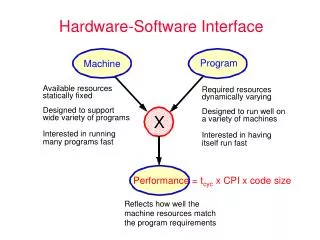
The Hardware Interface. Chapter 2. Key concepts in chapter 2. General and special-purpose registers Processor modes: user and system Memory addressing physical (or absolute) addresses and address space logical addresses and address space I/O address space Interrupts

E N D
The Hardware Interface Chapter 2 Crowley OS Chap. 2
Key concepts in chapter 2 • General and special-purpose registers • Processor modes: user and system • Memory addressing • physical (or absolute) addresses and address space • logical addresses and address space • I/O address space • Interrupts • I/O devices and memory-mapped I/O Crowley OS Chap. 2
CRA-1 organization Crowley OS Chap. 2
General-purpose registers • 32 general registers, each 32 bits long • r0: always 0 • r1: return values of functions • r8, r9, r10, r11: function parameters • r29: frame pointer • r30: stack pointer • r31: return address for function call instruction Crowley OS Chap. 2
Special-purpose registers • ia: address of the next instruction to execute • psw: program status word, processor state • base: memory-mapping base register • bound: memory-mapping bound register • iia: saves ia during an interrupt • ipsw: saves psw during an interrupt • ip: saves interrupt-specific data • iva: address of the interrupt vector area • timer: interval timer Crowley OS Chap. 2
Processor modes • psw bit 0: 1 if system mode, 0 if user mode • User mode • a user program is running • certain instructions are not allowed • memory mapping (base and bound) is enabled • System mode • the operating system is running • all instructions are allowed • memory mapping (base and bound) is disabled Crowley OS Chap. 2
Instruction set of the CRA-1 • Load and store register (including control registers when in system mode) • Load and store all register (for saving state) • Move register to register • System call • Return from interrupt • Plus many others not relevant here Crowley OS Chap. 2
CRA-1 memory and addressing • 32-bit physical (a.k.a. absolute) addresses • 8-bit bytes • physical address space: 0 to 0xFFFFFFFF • memory address space: 0 to 0xEFFFFFFF • I/O address space: 0xF0000000-0xFFFFFFFF • 32-bit logical addresses • mapped by base and bound registers • defines a logical address space Crowley OS Chap. 2
Interrupts • System call: program executed a syscall • Timer: timer register went from 1 to 0 • a non-zero timer counts down every microsecond • Disk: a disk operation completed • Program error • ip=0: undefined instruction • ip=1: illegal instruction in user mode • ip=2: logical address >= bound register Crowley OS Chap. 2
Interrupt processing • Steps in handling an interrupt • psw saved in ipsw, psw set to 0 • interrupt parameter (if any) placed in ip register • ia saved in iia • new is taken from interrupt vector area (offset depends on which interrupt it is) • timer and disk interrupt can be masked (recorded but delayed) by setting psw bit 0 Crowley OS Chap. 2
CRA-1 I/O devices • Memory-mapped I/O • device registers are in the physical address space • Disk controller and disk • 4 Kbyte disk blocks • 20 bit disk block numbers Crowley OS Chap. 2
Disk controller information • const int BlockSize = 4096;enum disk_command {LoadBlock=0, StoreBlock=1};struct disk_control_reg { unsigned int command : 1; unsigned int interrupt_enabled : 1; unsigned int disk_block : 20; unsigned int padding : 10;};volatile disk_control_reg *Disk_control = (disk_control_reg *)0xF0000000;void **Disk_memory_addr = (void **)0xF0000004;enum disk_status { DiskIdle=0, DiskBusy=1 };struct disk_status_reg { unsigned int busy : 1; unsigned int padding : 31;};disk_status_reg *Disk_status = (disk_status_reg *)0xF0000008; Crowley OS Chap. 2
Simple OS code and simulators • CRA-1 Simple OS • code in the book, but there is no simulator • MIPS Simple OS • code in distribution, runs on UNIX systems • a number of changes in the low-level code that interfaces to the hardware • Java Simple OS • code in distribution, runs on Java 1.1 systems and Java 1.1 browsers • a number of changes in the low-level code that interfaces to the hardware Crowley OS Chap. 2
MIPS Hardware Interface • TBD Crowley OS Chap. 2
Java Hardware Interface • TBD Crowley OS Chap. 2