Download

1 / 25
640 likes | 2.02k Views
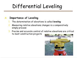
Profile Leveling. Definition. A surveying method that yields elevations at definite points along a reference line. Profile leveling establishes a side view or cross sectional view of the earth ’ s surface. Primary use is for utilities: Highways Canals Sewers Water mains Sidewalks

E N D
Definition A surveying method that yields elevations at definite points along a reference line. Profile leveling establishes a side view or cross sectional view of the earth’s surface • Primary use is for utilities: • Highways • Canals • Sewers • Water mains • Sidewalks • Retaining walls • Fences All of these need accurate information about the topography along the route.
Characteristics May be a single segment. May be multiple segments which change directions with angle points. May be straight segments connected with curves.
Procedure • It is a common practice to use a procedure called stationing. • Stations are established at uniform distances along the route. • Standard station distance is 100 feet. • Half or quarter stations are used when the topography is very variable. • The distance from the starting point to the station is used as the station identification.
Procedure-cont. Foresights are recorded at each standard station and at additional stations as needed to define the topography of the route. These foresights are called intermediate foresights. Intermediate foresights: foresights taken at stations that are not used as benchmarks or turning points. • Purpose is to define the topography along the route. • High points • Low points • Changes in slope • Critical points Roads Highway Gutters Sidewalks
Procedure-cont. When distances to foresights become too long or when the terrain obstructs the view of the instrument, turning points are established. Foresights on turning points and benchmarks are true foresights. Profile leveling is differential leveling with the addition of intermediate foresights.
Example One Determine the profile for a proposed sidewalk that connects two existing sidewalks. Step one: establish the standard stations. Note: the last station is established even though it is not a standard station.
Example One-cont. Step 2: Determine the sites for the critical features. In this example, the critical features are the rapid change is slope at 337.5 and the road at 489.6. Note a station was al20 established at 546.4 to define the width of the road and any changes in elevation across the road.
Example 1-cont. Step 3: Set up the instrument and start recording data. The first rod reading is a backsight on the first sidewalk (benchmark) to establish the height of the instrument. Note: in this case the true elevation of the benchmark is unknown, therefore 100.00 feet is used.
Example One-cont. Step 4: Start recording the rod readings for each station. Note: this station is not used as a benchmark or as a turning point, therefore is is an intermediate foresight.
Example One-cont. The rod reading for each station is recorded on the appropriate line of the table. Note: the rod reading for station 489.6 is placed in the FS column because this station will be used as a turning point.
Example One-cont. Every time the instrument is moved, a backsight is used to reestablish the height. Step 6: the instrument is moved so the remaining stations can be reached.
Example One-cont. The last step is closing the loop.
This is excessive slope according to ADA standards. Plot of Profile Data Potting the data helps answer questions as, “Will the slope of the sidewalk be acceptable?”. In this example the steepest slope appears to be between stations 300 and 327.5. The slope at this point is:
Excel Calculation of Slope It is easy to calculate all of the slopes using a spreadsheet.
Additional uses of Profile Plot Profile plots are also very useful for other utility routes such as drain pipes. Drains are design with a uniform slope. Plotting the drain on the profile provides a visual of the relationship between the earth’s surface and the drain. Assume the survey was completed for a drain pipe instead of a sidewalk. Also assume the starting elevation of the drain pipe is at three feet below the surface at station 0.0 and that the desired slope is 1%.
It should be oblivious that this design has problems because at station 550 the drain pipe is above ground.
One of the advantages of spread sheets is doing “What if” scenarios. What if the drain slope was changed to 0.5%? The way this spread sheet was set up changing the % slope required change one value. If the drain pipe will function correctly at 0.5% slope, this would be a workable alternative.
What if the profile survey was for an open drain? In this situation questions like, “What is the maximum depth of the ditch can be determined?”. Plots of profile data can be used for many other types of design questions. At station 200 the elevation of the surface is 106.6 ft and the elevation of the bottom of the ditch is 98.0 ft. 106.6 - 98 = 8.6 ft The ditch will be 8.6 feet deep at that point.
The answer to this question is determined by the ditch design. Most drainage ditches have a trapezoidal cross section shape. The bottom width is determined by the anticipated flow rate through the ditch. The side slopes are usually either 2:1 or 3:1 ratio. Assuming a ditch bottom width of 15 ft. This provides enough information to answer another design problem. How much space will be required for the ditch at the widest point? The space required is 16 ft + 15 ft + 16 ft = 47 ft