Download
1 / 101
1.01k likes | 1.13k Views
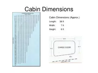
2013 Cabin Construction Packet. Following slides will assist with completing the required wall sections, transverse sections, and elevations. Note: dimensions are shown only for your information / you do not need to include on your work. Complete Transverse Section:.

E N D
2013 Cabin Construction Packet Following slides will assist with completing the required wall sections, transverse sections, and elevations. Note: dimensions are shown only for your information / you do not need to include on your work.
Start with footing and foundation wall. Footing has “Keyway” struck in it via 2x4. Exact dims loose / aim for 1 ½” deep.
Floor Pack: Add first stage of carpentry. FYI Actual lumber dimensions: 2x4: 1.5x3.5 2x6: 1.5x5.5 2x8: 1.5x7.25 2x10: 1.5x9.25 2x12: 1.5x11.25 Etc…
Draw a #5 anchor bolt. Note: top of bar stock would be threaded at least 1” down.
Move it into position. *It really is installed while concrete is wet / before the deck phase begins.
Start Stud Walls: Offset the top edge of the plywood subfloor to the desired height of the walls. We’ll use 8’.
Stud Walls: Next draw a line from the new offset line down to the top of the plywood and offset (to the right) for a 2x4 (3.5”).
Stud Walls: Add…
Stud Walls: And add…
Add ¾” sheathing from top of double plate to bottom of box sill. *Note lines are offset at .25” to depict ply layers. *Sheathing is typically either plywoodor OSB (Orientated Strand Board).
Rafter / Roof Phase: Roofs are “measured” by rise over run. Common terms would be 5:12, 6:12, 8:12, 12:12, etc. The second number is typically always 12. The lower the first number, the less steep the roof. The higher the first number, the steeper the roof. Our cabin will have a 6:12 pitch.
Start by drawing a 12” horizontal line left to right. Next, draw a 5” vertical line. Connect the ends.
Next, move the diagonal line from it’s lower left endpoint to the top right endpoint of the double plate.
Offset rafter height: we’ll use a 2x12 rafter to ensure enough depth for proper insulation (R38), so use 11.25 offset.
Roof Overhang: Offset the outside sheathing edge 3’-5”.
Use fillet (radius 0) to merge the lines together. *Note: be sure to trim the lower rafter line out of the double plate & plywood.
Add 5/8” sheathing on top of the rafter & 2x10 block above the double plate.
Pan/zoom to display FULL hatch area on screen. • “H” enter. • Select Hatch pattern as Ansi37
Select a pink color (241 works well) • Change scale to 10
Hover your mouse in the-fully-enclosed hatch area and left click. The hatch pattern, color, and scale will fill the area. Finish by clicking on “Close Hatch Creation” button in upper right corner.
Getting there! Your drawing should be complete in terms of structure and enclosure… Now a just a few details… Next steps: • Rebar in footing • Add a grade line (dirt level) • Hatch areas below grade • Insulate
Show Rebar (reinforcement bar) in footing. *These would be added during the pour process. **Green lines to be erased- only used to locate… Draw two circles with 5/8” diameter (5/16” radius). They must not be higher than 2” off the bottom of the footing and no lower than 1 ½” above ground level.
Hatch footing and foundation wall using “AR-CONC” at scale “1”. Color should be concrete color / a light gray.
Draw grade line 6” below top of foundation wall. Line must be sloped away from wall (drain away). Line should look like example; it’s not totally flat (it’s earth not a parking lot!)… and should not be too jagged looking (i.e. moonscape).
Add grass… Offset grade lines 3” up and draw a few “blades of grass.”
OPTIONAL / P.S.A.: A brick sill is created by framing a “block” in the form before the concrete is poured. This creates a lower level in the foundation wall for masonry to start on. The level may be flush or even below grade line. A brick sill aesthetically allows for the masonry to appear to be rising right out of grade.
Mortar Ramp: A Mortar Ramp will help water flow to the drain tile. Draw a line from the top left (outside) corner of the footing back to the foundation wall. Angle of line should be 30 degrees or less. Basically, you just need a “ramp” to encourage water to run down off the top of the footing. Real construction: simply jump in the hole with a bucket of mortar and a trowel and hand apply.
Add Rigid Insulation: *Every inch of rigid insul thickness = a thermal rating of R5. Higher the R value, the better the heat/cool retention. Start the rigid at the top of the mortar ramp, show as 1.5” thick, and chose a height that ends just below grade level (mine was 30”). Stop the insul just below grade as its not aesthetic to look at (but obviously this leaves a weak spot in the thermal building envelope).
Drain Tile: A drain tile is a corrugated and perforated flexible hose (typically black). Depending upon soil conditions, it may have a “sock” wrapped on it to prevent sand / dirt from seeping into the hose and blocking flow. Goal of the drain tile is to collect ground water and pitch it down to collection points (sump pit) where it can be pumped away from structure. The red lines represent where the drain tile may fall as it pitches high to low along the footing perimeter. Pitch of the drain tile may be as little as 1/8” per foot.
Creating Hatch boundaries for undisturbed soil, gravel, top soil, and compacted fill (soil). Use “pline” to draw the red line in step 1. Use “pline” to draw the green lines in step 2.
Hatch the top soil: ANSI37 pattern Scale 5 Color 36
Hatch the compacted fill: EARTH pattern Scale 8 Angle 45 Color 35
Hatch the undisturbed soil: EARTH pattern Scale 8 Angle 0 Color 35
Hatch the gravel: GRAVEL pattern Scale 2 Color 253
Draw 4” Concrete Floor Slab. Draw a line to close the space (red line) and hatch. Match prop (“MA”) of hatch to foundation wall. Draw boundary line (yellow line) for gravel under slab and hatch. Hatch mortar ramp with ARSAND, scale .5, color… well, mortar color…
What your drawing should look like. Next: Batt Insulation (Pink Panther stuff)
To depict Batt Insulation, first check to see if the linetype is loaded into you CAD environment. Pull down the Properties icon, check the line style menu for “BATTING”… if you don’t have it, select “Other” and then hit the “Load” button upper right corner of the new menu. Select BATTING and click ok.
Draw a 24” horizontal line from the mid of your box sill going left. Select the line (click on it) and pull down your linetype menu; assign BATTING. Scale of the line might need some adjusting… See next slide…
Left click on the BATT line and then right click. Scroll down to 2nd from bottom: “Properties.” A menu will appear on left side of your screen. Drive to Linetype scale and drive the number up or down depending on how your line looks. End goal: make it fit inside the floor joist bay. Last step: make the color pink.
Next: draw line down mid of stud bay and match (ma) to batt insulation line in floor joist bay. Adjust LT (linetype) scale… (example went to 0.1 to fit).
Rafter Insulation: Create a hidden line with 1” offset from inside plywood edge / top of rafter edge. This represents a vent cavity allowing for air to flow from ridge to eave. Next, draw a BATTING line to represent the insulation (LT scale 0.35 worked for my drawing).