Download
1 / 16
190 likes | 391 Views
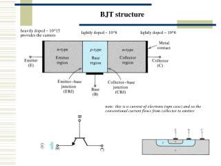
BJT Emitter Stabilized Bias. ELEC 121. Improved Bias Stability. The addition of R E to the Emitter circuit improves the stability of a transistor output

E N D
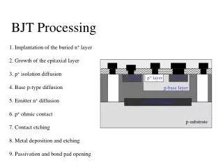
BJT Emitter Stabilized Bias ELEC 121
Improved Bias Stability • The addition of RE to the Emitter circuit improves the stability of a transistor output • Stability refers to a bias circuit in which the currents and voltages will remain fairly constant over a wide range of temperatures and transistor forward current gain () • The temperature (TA or ambient temperature) surrounding the transistor circuit is not always constant • Therefore, the transistor is not a constant value ELEC 121
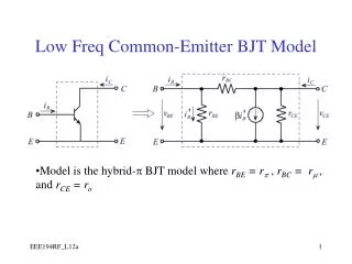
BJT Emitter Bias • Draw Equivalent Input circuit • DrawEquivalent Output circuit • Write necessary KVL and KCL Equations • Determine the Quiescent Operating Point • Graphical Solution using Loadlines • Perform a Computational Analysis ELEC 121
Emitter-Stabilized Bias Circuit Adding an emitter resistor to the circuit between the emitter lead and ground stabilizes the bias circuit over Fixed Bias ELEC 121
Base-Emitter Loop ELEC 121
Equivalent Network ELEC 121
Reflected Input impedance of RE ELEC 121
Base-Emitter Loop Applying Kirchoffs voltage law: - VCC + IB RB + VBE +IE RE = 0 Since: IE = ( + 1) IB We can write: - VCC + IB RB + VBE + ( + 1) IBRE = 0 Grouping terms and solving for IB: Or we could solve for IE with: ELEC 121
Collector-Emitter Loop ELEC 121
Collector-Emitter Loop Applying Kirchoff’s voltage law: - VCC + IC RC + VCE + IE RE = 0 Assuming that IE IC and solving for VCE: VCE=VCC – IC (RC + RE) If we can not use IE IC the IC = IE and:VCE=VCC – IC (RC + RE) Solve for VE: VE = IE RE Solve for VC: VC = VCC - IC RC or VC = VCE + IE RE Solve for VB: VB = VCC - IB RB or VB = VBE + IE RE ELEC 121
Transistor Saturation At saturation, VCE is at a minimum We will find the value VCEsat = 0.2V For load line analysis, we use VCE = 0 To solve for ICSAT, use the output KVL equation: ELEC 121
Load Line Analysis The load line end points can be calculated: At cutoff: At saturation: ELEC 121
Design of an Emitter Bias CE Amplifier Where .1VCC VE .2VCC And .4VCC VC .6VCC ELEC 121
Emitter Bias with Dual Supply ELEC 121
Emitter Bias with Dual Supply Input Output ELEC 121