Download
1 / 20
200 likes | 337 Views
FAIR Synchrotrons SIS100/300. Peter Spiller FAIR monthly May 18, 2007. Beam Parameters. Bottleneck is SIS18 ! Challenging and unique operation at the limit to vacuum instability defines the number of particles in SIS100. Technical Subsystems. Sixfold Symmetry

E N D
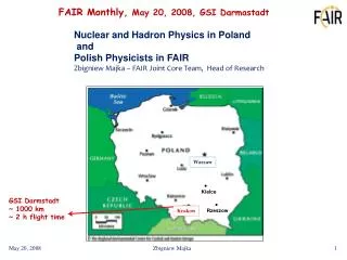
FAIR Synchrotrons SIS100/300 Peter Spiller FAIR monthly May 18, 2007
Beam Parameters Bottleneck is SIS18 ! Challenging and unique operation at the limit to vacuum instability defines the number of particles in SIS100
Technical Subsystems • Sixfold Symmetry • Sufficiently long and number of straight sections • Reasonable line density in resonance diagram • Good geometrical matching to the overall topology S1: Transfer to SIS300 S2: Rf Compression (MA loaded) S3: Rf Acceleration (Ferrite loaded) S4: Rf Acceleration (Ferrite loaded) S5: Extraction Systems (slow and fast) S6: Injection System plus RF Acceleration and Barrier Bucket The SIS100 technical subsystems define the length of the straight sections of both synchrotrons S3 S2 S4 S1 S5 S6
SIS100/300 Sections S1 S4 S2 S5 S3 S6 SIS100: Distribution of all devices completed SIS300: Distribution of devices ongoing
Two Stage Synchrotron SIS100/300 • 1. High Intensity- and Compressor StageSIS100 with fast-ramped superconducting magnets and a strong bunch compression system. Intermediate charge state ions e.g. U28+-ions up to 2.7 GeV/u Protons up to 30 GeV FBTR: Bρ= 100 Tm - Bmax = 2 T - dB/dt = 4 T/s (straight dipoles) Bρ= 100 Tm - Bmax = 1.9 T - dB/dt = 3.8 T/s (curved dipoles • 2. High Energy- and Stretcher StageSIS300 with superconducting high-field magnets and stretcher function. Highly charges ions e.g. U92+-ions up to 34 GeV/u Intermediate charge state ions U28+- ions at 1.5 to 2.7 GeV/u with 100% duty cycle FBTR: Bρ= 300 Tm - Bmax = 6 T - dB/dt = 1 T/s (short, straight dipoles) Bρ= 300 Tm - Bmax = 4.5 T - dB/dt = 1 T/s (long curved dipole)
Magnets: SIS100 Magnet Redefinition • Sagitta of straight dipoles has defined the acceptance • Beam displacement in the fringe field and middle of the straight magnets enhance errors • Maximum required dipole and quadrupole field too high • Field properties questionable • Increased apertures compared to the original Nuclotron magnets: a) Higher current requirements b) Enhanced AC loss and reduced quench stability c) Higher stored energy > Quench protection scheme difficult and requires cable modification (number of strands) Curved SIS100 Dipole Magnet Prolongated SIS100 Quadrupole Magnet
Magnets: SIS300 Magnet Redefinition The cos magnets (SIS300) consume more space than superferric magnets (SIS100) and are just suitable for the small circumference. a) Not sufficient space in the arcs for the FBTR doublet lattice cell > FODO lattice b) Dipole sagitta limits the acceptance (acceptable in strong focusing lattices) Reason: The effective field length in iron dominated magnets is longer than the yoke. The effective field length in co magnets is much Shorter than the cold mass. SIS100 defines the ratio between the straight section and arc length.
Magnets: Magnet Development • Several model magnets for R&D on AC loss, field quality and mechanical aspects (JINR) • Three prototype dipole magnets for SIS100 are in production • (two straight (BNG, JINR) and one bent (BINP) • Design review approval – Delivery in 2008 • Bent SIS300 prototype dipole magnet is in preparation (INFN) • String test required (2009-2010) approval for cryomagnetic integration of all components
Structure: SIS100 Focusing Modules SIS100 missing dipole, doublet structure has kept unchanged. Two standard quadrupole units, but many exceptions ! Big engineering effort for preplanning of cryomagnetic modules. • Quadrupol unit of the arc • includes sextupole, BPM and • collimator (used also for pumping) • Quadrupole unit of the straights includes BPM, sextupole and pumping chamber Dipole Moduls
Structure: SIS300 Structure Redefinition FBTR SIS 300 Lattice Doublet Lattice base on short straight dipoles New SIS 300 Lattice FODO Lattice based on long (and short) curved dipoles Small ring circumference and matching to SIS100 geometry requires FODO lattice in SIS300 and curved dipole magnets. Advantages a) chromaticity correction without significant DA reduction b) slow extraction with reasonable s.c. septum strength
Extraction The new missing dipole arc of SIS300 avoids lateral displacement between SIS100 and SIS300 and enables the bypassing of the SIS100 extraction line and thereby vertical extraction of both synchrotrons.
Extraction: SIS100 Extraction Section 3D conceptual design study for the SIS300, 3.5 T s.c. extraction septum Start prototyping in 2007. Prototype ramped, bipolar kicker in preparation. Halo Scraper Electrostatic Septa Bipolar Kicker System Magnetic Septa and Emergency Dump Lambertson Septum
Transfersystem SIS100 – SIS300 Tight geometrical and matching constaints. Revision required because of new SIS300 FODO lattice. Design study collaboration FSY and ACCEL. Optical and technically feasible solution found.
Rf: Overview Ferrit loaded accel. cavity MA test cores at GSI SIS18 bunch compressor
Rf: SIS100 Acceleration Sections • Acceleration Cavity: • Design study completed (BINP) • Engineering study completed • Start prototype manufacturing expected for 2007 16 ferrite cavities for acceleration in section S3 and S4
Rf: SIS100 Compression Section • Compression Cavities: • SIS18 compression system with very similar techn. parameters completed 16 MA compression cavities in section S2
Synchrotron Main Supply Buildings Document „Specifications for Synchrotron Buildings“ includes main accelerator aspects • Table of floor space requirements • Tables for cranes and double floor • Distribution of supply units for all buildings and floors • Cable planning started • General specifications plus Load List
SIS100/300 Labyrinth and Supply Tunnel Building optimization for cryogenic and media supply required
HEBT: Revised FBTR Topology • Matched to changes in CR, RESR, HESR and Super-FRS layout • HESR extension considered • N.c. beam line to pbar Target, PP, AP • Gaps closed to extraction from SIS18 and SIS100/300 • Matched to zero displacement between SIS100 and SIS300 • Adapted to changed SIS100/300 magnet design • Second beam line for PP and PP perpendicular • p beam line from SIS18 to HESR
Status of Optical Design and Next Steps • Present status Linear layout with chromatic- and space charge effects main for beam transport systems completed and approved (beside a few lines around the storage rings) Higher order layout for Super-FRS Higher order layout with chromatic effects and tracking studies for pbar-separator • Next or ongoing design steps Prove of technical feasibility (e.g. collisions) Integration of beam diagnostics and correctors (presently proceeding) Technical pre-design (e.g. cryogenic system and supply, warm magnet design) Coordination with civil construction (e.g. alignment, building floor, infrastructure) Modification and optimization of supply buildings (presently proceeding) Building 4 and 4a