Download
1 / 19
210 likes | 884 Views
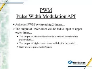
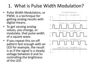
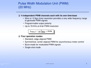
Pulse Width Modulation. PWM Features. General Features Four Channels, one 16-bit counter per channel, One common clock generator, providing 13 different clocks, One Modulo n counter providing eleven clocks, Two independent linear dividers working on modulo n counter output,

E N D
PWM Features • General Features • Four Channels, one 16-bit counter per channel, • One common clock generator, providing 13 different clocks, • One Modulo n counter providing eleven clocks, • Two independent linear dividers working on modulo n counter output, • Channel Programming • Independent enable/disable commands, • Independent clock selection, • Independent period and duty cycle, with double buffering system, • Programmable selection of the output waveform polarity, • Programmable center or left aligned output waveform.
View of the external PWM’ Signals • 4 Multiplexed Channel outputs with PIOA lines • Dedicated high current output pad • Multiplexed to PA0, PA1 and PA2 (respectively for PWM0, PWM1 and PWM2) allow the user to drive external circuitry with load current up to 16 mA (instead of 8 mA for standard pads)
PWM into the AT91SAM7S • PMC has to be programmed 1st for PWM to work: Clock Enabling • Set the PMC_PCER (Peripheral Clock Enable Register), bit 10 (PID10). • PIO Controller has to be programmed for the pins to behave as intended • Disable targeted PIO line(s) by using PIO_PDR (PIO Disable Register) as shown below • Select between Peripheral A or B, respectively, in PIO_ASR or PIO_BSR in order to select the PWM peripheral output channel(s) on the right pad(s).
PWM CHANNEL PWM Architecture • The PWM Peripheral can be split up into two parts • 1°- The PWM Controller which is made of: • Clock Generator => Clock generation from the Master Clock (MCK) • Channel Control => Enable/Disable Channel • Interrupt Generator • 2°- Channel Modules: • Clock Selector • Channel Running Mode Manager • Duty Cycle and frequency Control • Counter value • Update register
PWM PWMC: Clock Generator PWM_MR (Mode Register) 27 24 23 16 11 8 7 0 PREB DIVB PREA DIVA 1, ½,1/3,..,1/255 1, ½,1/3,..,1/255 CLKA MCK CLKB
PWM PWM PWMC: Channel and Interrupt Management • At PWMC level, the user can, independently, enable/disable each channel PWM_DIS (Disable Register) PWM_ENA (Enable Register) 3 0 3 0 CHID3 CHID2 CHID1 CHID0 CHID3 CHID2 CHID1 CHID0 PWM_SR (Status Register) 3 0 CHID3 CHID2 CHID1 CHID0 • The user can use the same control panel at interrupt level plus the dedicated mask register PWM_IDR (Interrupt Disable Register) PWM_IER (Interrupt Enable Register) 3 0 3 0 CHID3 CHID2 CHID1 CHID0 CHID3 CHID2 CHID1 CHID0 PWM_IMR (Interrupt Mask Register) PWM_ISR (Interrupt Status Register) 3 0 3 0 CHID3 CHID2 CHID1 CHID0 CHID3 CHID2 CHID1 CHID0
Set up the PWMC in your Application • Disable the PIO lines and select the right peripheral between A or B at multiplexing level. PIO and PWM lines • For power saving consideration, the PWM ‘s clock is stoppped at Power Management Controller level by default. Enable the PWM Clock • Set up the targeted clocks which will be used for the 4 PWM Channels. Set up the Clock Generator Channel Enabling • These tasks can be performed after the complete channel setting Interrupt Enabling
PWM CHANNEL Set up a PWM Channel • Per channel: • Channel Mode Register: Select the running mode of the channel • Duty Cycle Register: 16-bit value to select the duty cycle of the signal • Period Register: 16-bit value to select the period of the signal • Counter Register: counter value • Update Register: Specific register to modify, synchronously, the Duty Cycle Register or the Period Register. PWM Channel 0,1,2 or 3 PWM Controller PeriodControl PWM pad Comparator Update Register Duty CycleControl CLKA ClockSelector CLKB MCK…. down to MCK/1024 Counter Interrupt
CHANNEL First Step: Clock Choice PWM_CMR (Channel Mode Register) • At Channel level, the Channel Mode Register allows the user to choose between the 13 sources from the clock generator 3 0 CLKA CPRE CLKB Channel’sCounter ClockGenerator
CHANNEL What is the best clock source ? • The PWM duty cycle quantum is the first criterion: • The user has to know his minimum requested accuracy at duty cycle level. The duty cycle control is managed through a 16-bit PWM_CDTY register. PWM_CDTY (Channel Duty Cycle Register) N value 15 0 CDTY • The duty cycle quantum depends on the value written in Period Register: • The M value is the required number of event in order to complete one PWM channel period (or half period in center-aligned mode) PWM_CPRD (Channel Period Register) M value 15 0 CPRD The PWM Channel period being equal to M source period. N will be from 0 up to M value. The higher M value, the higher the N value can be, the lower the quantum.
PWM CHANNEL Example of different PWM accuracy • In this first choice, the duty cycle quantum will be 1/75 of a period Clock Generator CLKA Clock Generator on(/64) = Channel PeriodRegister = 75 750 kHz 10 kHz CLKB 48 MHz • For the same period, the duty cycle quantum will be 1/4800 of a period. Clock Generator CLKA Clock Generator on(1) = Channel PeriodRegister = 4800 48 MHz 10 kHz CLKB 48 MHz
CHANNEL How to modify a channel Period or a channel Duty Cycle value ? • Before to enable the PWM Channel at PWM Controller level (PWM_ENA Register):The user will be able to write directly into the PWM_CDTYx or PWM_CPRDx of this channel, respectively, for a duty cycle or period change. • As soon as this PWM channel has been enabled:It is not possible to write into these previous registers. The user will have to use the Channel Update Register in order to modify one of the previous value. • The contain of the Update register is put into the PWM_CDTY or PWM_CPRD according to the value of CPD value in PWM_CMR PWM_CMRx (Channel Mode Register) 10 3 0 CPD CPRE PWM_CDTYx 0 PWM_CUPDx PWM_CUPDx 1
CHANNEL Channel Update Register: PWM_CUPD • Why use it: • In running mode, modifying the duty cycle or the period value can be done only via PWM_CUPD, • The duty cycle or the period modification is going to be taken synchronously into account at the end of the period in progress, • How use it: • Before to write in PWM_CUPD, the user will have to be sure that the last write has been take into account. In other case, the previous data will be overlaid by the last one. • Use the bit CPD, in PWM_CMR register, in order to select a duty cycle or period modification, • Write the data into PWM_CUPD register. Note: It is not possible to modify, in the same PWM period for one channel, the duty cycle AND the period values.
PWM CHANNEL PWM_CUPD Write method • Polling or interrupt methods can be used: • A flag rises after an end of channel period (channel 1 for example) PWM_ISR (Interrupt Status Register) • Reading PWM_ISR automatically clears CHIDx flags 3 0 CHID3 CHID2 CHID1 CHID0 0 0 0 0 PWM_ISR (Interrupt Status Register) 3 0 CHID3 CHID2 CHID1 CHID0 0 0 1 0 • Modifying duty cycle or period value in channel 1 can be possible without overlaying risk at PWM_CUPD level.
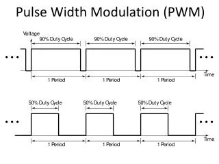
CHANNEL First Working Mode: Left-aligned PWM_CMR (Channel Mode Register) When the PWM Counter reach the period value, it is cleared. 9 8 CALG=0Lelt-Aligned Mode CPOL PWM_CPRD PWM_CDTY 0 CPOL= 0 CPOL= 1
CHANNEL Left-aligned Limitation in Multi-Channel use • The left-aligned working mode does not allow to avoid overlapped transition in Multi-channel use In Left-aligned Mode:One event depends on the duty cycle value and the other depends on the period value.For the same period, there will be overlapped event PWM_CPRD0 PWM_CDTY0 Channel 0Output The period of both Channels are equal (PWM_CDTY0 - PWM_CDTY1) Channel 1Output PWM_CPRD1 PWM_CDTY1
CHANNEL Second Working Mode: Center-aligned PWM_CMR (Channel Mode Register) 9 8 CALG=0Lelt-Aligned Mode CPOL PWM_CPRD Count down Count up PWM_CDTY 0 CPOL= 0 CPOL= 1
CHANNEL Center-aligned: Non-overlapped event Method • The center-aligned working mode allows to avoid overlapped transition in Multi-channel use PWM_CPRD0 PWM_CDTY0 Channel 0Output (PWM_CDTY0 - PWM_CDTY1) Channel 1Output PWM_CPRD1 PWM_CDTY1