Download
1 / 29
300 likes | 434 Views
Designing Digital Circuits Using Hardware Description Languages (HDLs). Lecture 4.5. Hardware Description Languages. ABEL Verilog VHDL. We will only cover ABEL and Verilog VHDL is taught in CSE 378. Designing a Digital Circuit. ABEL. Advanced Boolean Expression Language An Example.

E N D
Designing Digital Circuits Using Hardware Description Languages (HDLs) Lecture 4.5
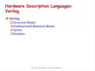
Hardware Description Languages • ABEL • Verilog • VHDL We will only cover ABEL and Verilog VHDL is taught in CSE 378
ABEL Advanced Boolean Expression Language An Example
ABEL The source file gates.abl
Verilog source code gates.v module gates(x,y,invx,invy,andd,orr,nandd,norr,xorr,xnorr); input x; input y; output invx; output invy; output andd; output orr; output nandd; output norr; output xorr; output xnorr; assign invx = ~x; assign invy = ~y; assign andd = x & y; assign orr = x | y; assign nandd = ~(x & y); assign norr = ~(x | y); assign xorr = x ^ y; assign xnorr = x ~^ y; endmodule
Pin numbers set it separate file:gates.ucf NET "x" LOC = "p11"; NET "y" LOC = "p7"; NET "invx" LOC = "p35"; NET "invy" LOC = "p36"; NET "andd" LOC = "p37"; NET "nandd" LOC = "p39"; NET "orr" LOC = "p40"; NET "norr" LOC = "p41"; NET "xorr" LOC = "p43"; NET "xnorr" LOC = "p44";
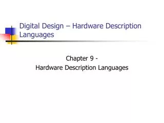
7-Segment Displays ABEL Verilog
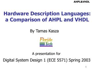
Covalent bonds -- Insulator http://electronics.howstuffworks.com/diode1.htm
Semiconductors Adding a very small amount of B or Ga to Si makes a p-type semi-conductor with a missing electron (a hole) Adding a very small amount of P or As to Si makes an n-type semi-conductor with an extra electron
Diodes + - http://www.mtmi.vu.lt/pfk/funkc_dariniai/diod/index.html
Turning on an LED This is what we use in Lab
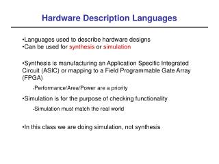
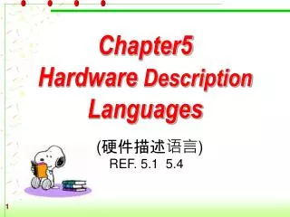
a f b g e c d 7-Segment Display a b c d e f g 0 1 1 1 1 1 1 0 1 0 1 1 0 0 0 0 2 1 1 0 1 1 0 1 3 1 1 1 1 0 0 1 4 0 1 1 0 0 1 1 5 1 0 1 1 0 1 1 6 1 0 1 1 1 1 1 7 1 1 1 0 0 0 0
a f b g e c d 7-Segment Display a b c d e f g 8 1 1 1 1 1 1 1 9 1 1 1 1 0 1 1 A 1 1 1 0 1 1 1 b 0 0 1 1 1 1 1 C 1 0 0 1 1 1 0 d 0 1 1 1 1 0 1 E 1 0 0 1 1 1 1 F 1 0 0 0 1 1 1
Makes this module available in higher-level modules hex7seg.abl MODULE hex7seg INTERFACE ([D3..D0] -> [a,b,c,d,e,f,g]); TITLE 'hex to seven segment display decoder' " a " --- hex-to-seven-segment decoder " f| g |b " --- " e| d |c " --- DECLARATIONS " Input Pins " D3..D0 PIN; D = [D3..D0]; " 4-bit input vector " Output Pins " [a,b,c,d,e,f,g] PIN ISTYPE 'com'; " 7-segment LED display segs = [a,b,c,d,e,f,g];
ON,OFF = 1,0; " for common cathode LEDs @radix 16; EQUATIONS "[ a , b , c , d , e , f , g ] when (D == 0) then segs = [ ON, ON, ON, ON, ON, ON, OFF]; when (D == 1) then segs = [OFF, ON, ON, OFF,OFF,OFF,OFF]; when (D == 2) then segs = [ ON, ON, OFF,ON, ON, OFF, ON]; when (D == 3) then segs = [ ON, ON, ON, ON, OFF,OFF, ON]; when (D == 4) then segs = [OFF, ON, ON, OFF,OFF,ON, ON]; when (D == 5) then segs = [ ON, OFF,ON, ON, OFF,ON, ON]; when (D == 6) then segs = [ ON, OFF,ON, ON, ON, ON, ON]; when (D == 7) then segs = [ ON, ON, ON, OFF,OFF,OFF,OFF]; when (D == 8) then segs = [ ON, ON, ON, ON, ON, ON, ON]; when (D == 9) then segs = [ ON, ON, ON, ON, OFF,ON, ON]; when (D == 0A) then segs = [ ON, ON, ON, OFF,ON, ON, ON]; when (D == 0B) then segs = [OFF, OFF,ON, ON, ON, ON, ON]; when (D == 0C) then segs = [ ON, OFF,OFF,ON, ON, ON, OFF]; when (D == 0D) then segs = [OFF, ON, ON, ON, ON, OFF, ON]; when (D == 0E) then segs = [ ON, OFF,OFF,ON, ON, ON, ON]; when (D == 0F) then segs = [ ON, OFF,OFF,OFF,ON, ON, ON]; END hex7seg HEX
MODULE SW7seg TITLE 'Switch hex code to 7-segment display' DECLARATIONS hex7seg interface([D3..D0] -> [a,b,c,d,e,f,g]); d7L FUNCTIONAL_BLOCK hex7seg; d7R FUNCTIONAL_BLOCK hex7seg; " INPUT PINS " SW7..SW0 PIN 11,7,6,5,4,3,2,1; " 8 toggle switches SW = [SW7..SW0];
" OUTPUT PINS " LEDR7..LEDR0 PIN 35,36,37,39,40,41,43,44 ISTYPE 'com'; LEDR = [LEDR7..LEDR0]; " Red LEDs [aa,bb,cc,dd,ee,ff,gg] PIN 57,58,61,62,63,65,66 ISTYPE 'com'; "Leftmost (tens) 7-segment LED display [a,b,c,d,e,f,g] PIN 15,18,23,21,19,14,17 ISTYPE 'com'; " Rightmost (units) 7-segment LED display
EQUATIONS LEDR = SW; [aa,bb,cc,dd,ee,ff,gg] = d7L.[a,b,c,d,e,f,g]; d7L.[D3..D0] = [SW7..SW4]; [a,b,c,d,e,f,g] = d7R.[a,b,c,d,e,f,g]; d7R.[D3..D0] = [SW3..SW0]; END SW7seg
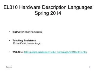
a f b g e c d module hex7seg(D,AtoG); input [3:0] D; output [6:0] AtoG; reg [6:0] AtoG; always @(D) case(D) 0: AtoG = 7'b1111110; 1: AtoG = 7'b0110000; 2: AtoG = 7'b1101101; 3: AtoG = 7'b1111001; 4: AtoG = 7'b0110011; 5: AtoG = 7'b1011011; 6: AtoG = 7'b1011111; 7: AtoG = 7'b1110000; 8: AtoG = 7'b1111111; 9: AtoG = 7'b1111011; 'hA: AtoG = 7'b1110111; 'hb: AtoG = 7'b0011111; 'hC: AtoG = 7'b1001110; 'hd: AtoG = 7'b0111101; 'hE: AtoG = 7'b1001111; 'hF: AtoG = 7'b1000111; default: AtoG = 7'b1111110; // 0 endcase endmodule hex7seg.v Verilog
SW7seg.v Verilog // Title : Toggle switches to 7-Segment Display // Author : R. E. Haskell module SW7seg(SW,LEDR,AtoG,AAtoGG); input [7:0] SW; output [7:0]LEDR; output [6:0] AtoG; output [6:0] AAtoGG; wire [6:0] AtoG; wire [6:0] AAtoGG; wire [7:0] LEDR; assign LEDR = SW; hex7seg d7L(.D(SW[7:4]),.AtoG(AAtoGG)); hex7seg d7R(.D(SW[3:0]),.AtoG(AtoG)); endmodule AAtoGG AtoG
#PACE: Start of PACE I/O Pin Assignments NET "AAtoGG<0>" LOC = "p66" ; NET "AAtoGG<1>" LOC = "p65" ; NET "AAtoGG<2>" LOC = "p63" ; NET "AAtoGG<3>" LOC = "p62" ; NET "AAtoGG<4>" LOC = "p61" ; NET "AAtoGG<5>" LOC = "p58" ; NET "AAtoGG<6>" LOC = "p57" ; NET "AtoG<0>" LOC = "p17" ; NET "AtoG<1>" LOC = "p14" ; NET "AtoG<2>" LOC = "p19" ; NET "AtoG<3>" LOC = "p21" ; NET "AtoG<4>" LOC = "p23" ; NET "AtoG<5>" LOC = "p18" ; NET "AtoG<6>" LOC = "p15" ; NET "LEDR<0>" LOC = "p44" ; NET "LEDR<1>" LOC = "p43" ; NET "LEDR<2>" LOC = "p41" ; NET "LEDR<3>" LOC = "p40" ; NET "LEDR<4>" LOC = "p39" ; NET "LEDR<5>" LOC = "p37" ; NET "LEDR<7>" LOC = "p35" ; NET "SW<0>" LOC = "p1" ; NET "SW<1>" LOC = "p2" ; NET "SW<2>" LOC = "p3" ; NET "SW<3>" LOC = "p4" ; NET "SW<4>" LOC = "p5" ; NET "SW<5>" LOC = "p6" ; NET "SW<6>" LOC = "p7" ; NET "SW<7>" LOC = "p11" ; SW7seg.ucf
Wiring up the top-level design ABEL [aa,bb,cc,dd,ee,ff,gg] = d7L.[a,b,c,d,e,f,g]; d7L.[D3..D0] = [SW7..SW4]; [a,b,c,d,e,f,g] = d7R.[a,b,c,d,e,f,g]; d7R.[D3..D0] = [SW3..SW0]; AAtoGG AtoG Verilog hex7seg d7L(.D(SW[7:4]),.AtoG(AAtoGG)); hex7seg d7R(.D(SW[3:0]),.AtoG(AtoG));