Download
1 / 22
220 likes | 346 Views
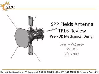
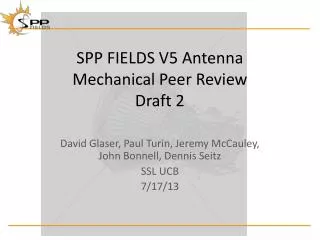
SPP FIELDS V5 Antenna Mechanical Peer Review. David Glaser, Paul Turin, Jeremy McCauley, John Bonnell , Dennis Seitz SSL UCB 7/17/13. Agenda. V5 Overview Thermal Antennas Antenna to PCB PCB Housing Mount to Mag Boom Antenna FEA Analysis Other TBDs. V5 Overview.

E N D
SPP FIELDS V5 Antenna Mechanical Peer Review David Glaser, Paul Turin, Jeremy McCauley, John Bonnell, Dennis Seitz SSL UCB 7/17/13
Agenda • V5 Overview • Thermal • Antennas • Antenna to PCB • PCB • Housing • Mount to Mag Boom • Antenna FEA Analysis • Other TBDs
V5 Overview V5 is an electric fields antenna, mounted on the SPP FIELDS Mag Boom, that will provide 3rd axis measurements complementary to the V1-V4 data. It has only a single Preamp Previous Design ~10 inches inboard Of SCM
V5 Overview Old Boom Design Shown Here SC X-axis (RAM Direction)
V5 Overview V5 is an electric fields antenna, mounted on the SPP FIELDS Mag Boom, that will provide measurements complementary to the V1-V4 measurements. It has uses a single op amp to cover the LF+MF DC-1MHz frequency range
V5 Overview Antennas Positronics DD15M0000G Housing V5 PCB Mass: ~70 g Housing Cover
Key Issue: V5 Thermal • Minimum expected temperature <<-100°C • Occasionally will see the Sun during SC slewing • Similar Preamps have been qualified for temperatures in this range • Temperature predicts need to be modeled • Including heat losses through harness • Options for Thermal Control Being Considered: • Blanketing • Resistive heater on PCB with “clean” power source • Heater on exterior of housing • Low emissivity coating on housing
Antennas 9.73” 4.00” • What drives the antenna length? • What surface finish for the antennas? PEEK Isolators Aluminum Aluminum wall
Antenna FEA Results 100G Quasi-static Load Load Direction 100G Stress < 10 ksi First Mode Frequency: 493 Hz Load Direction
Antenna to PCB Connection A single photoetchedBeCu part makes contact between the two antennas and the PCB
V5 PCB Circuit Board Currently 1.41” x 0.85” Layout 1.15” x 0.77” Max Component Height with Headroom: Top 0.34” (8.6mm) Bottom 0.056” (1.4mm)
V5 Housing • Housing and Cover are aluminum • 0.10” wall thickness • PCB mounts to Cover with 4X #0-80 screws • Mounts to Mag Boom with 2X #4-40 Screws 1.07” 1.09” 1.71”
With Backshell Glenair, 557T186
V5 PCB to DD15 Connector Want to minimize housing size, but space is tight
FEA Model For Antennas Removed Holes from Box Removed Hex Nut (Interference) Fixed at Mounting Holes
Other TBDs • Connector to PCB Wires/Connections • Harness • FEA with Connector & Backshell • Qualification Plan
PCB Layout • Heater resistor is R9 • Layout area could be reduced by having an external heater • C1, C2 might be reduced or eliminated, but that might lower bandwidth (TBD)