Download

1 / 16
160 likes | 386 Views
Table Top Shielded Antenna Anechoic Chamber for Bluetooth Applications. By Dan Pulito and Jason Blackman. Motivation. Kodak desired an environment in which data rate and power measurements were capable of being measured Extended in order take automated antenna measurements

E N D
Table Top Shielded Antenna Anechoic Chamber for Bluetooth Applications By Dan Pulito and Jason Blackman
Motivation • Kodak desired an environment in which data rate and power measurements were capable of being measured • Extended in order take automated antenna measurements • Finished design is to provide an environment for other senior design teams to test their wireless projects for antenna radiation and signal power.
Overview, What has been done? • An aluminum box was donated by Kodak and adjustments were made to prevent RF radiation from leaking from outside to inside and vice versa • Calculations were done in order to determine if the size of the box was adequate for the application and also to determine antenna placement • The box was then padded with RF absorbent foam • A platform and motor were implemented to perform antenna measurements • Software was written to synchronize motor angle and measurements taken on a spectrum analyzer • A known antenna with known gain was measured to calibrate loss in the system and a sample antenna was measured
Project Requirements Engineering Specifications Tasks Added at DDR
Size and Position Analysis • The analysis of the position of the antennas, and the verification that the size of the box meets the requirements was done in the DDR • The box dimensions are: 9”x 27” x 37” • It was found that at a frequency of 2.4 GHz, the antenna separation should be at minimum 21 inches • To reduce skipping waves, the antennas should be placed very close to the minimum distance based on the far-filed criteria so as to reduce shallow angles • Finally, to meet the criteria, the antennas were placed 4.5 inches from the bottom, 13.5 inches from the two side rails, and 21 inches apart.
Platform (Thank You Professor Slack) • A Platform was built to encase the motor and also to lift the box up in order to allow the motor to be installed from beneath the box. • 37”x 24” • Features compartment for the motor • Two wooden pieces and L-brackets hold the box in place while on the platform
Wideband Antenna • A wideband Antenna was designed with a return loss of -15 dB between 2 to 4.8 GHz. • The design features two resonances allowing a good frequency response over a wide range • Utilizes a distinct patch geometry as well as etching in the ground plane
Rotating Platform • The antenna to be tested is initially facing 90° to the right, where directly facing the transmit antenna is 0° • It rotates counter clockwise in steps of about 1° • At each step, a power measurement is taken from the spectrum analyzer • This continues for half of a revolution, until the antenna is facing the opposite direction that it started in
Motor Controller • The PC (LabVIEW) sends a signal (via the DAQ) to the MCU telling it to rotate the motor • The MCU sends a serial command to the motor controller to get the motor to rotate, then monitors the encoder feedback until the next step is reached • The MCU then signals to the PC (via the DAQ) that the next step has been reached • The PC acquires the power reading from the spectrum analyzer and displays it graphically and also writes it to a text file • The MCU signals to the PC when a full cycle (180°) is complete
LabVIEW • The instrument, frequency, span and ref level are selected before running • The full span is displayed on the upper smaller graph at each step • The peak power value for each step is plotted on the lower graph • After a full cycle is complete, a text file with all of the peak power measurements is saved for use in Matlab or Excel
Project Status • The programming of the motor and the spectrum analyzer are synchronized, meaning, the Tektronix Spectrum analyzer is programmed to make a measurement every time the motor makes a movement • The antenna has been designed and simulated in software. The design of the patch has been etched and four samples were produced. However, due to the manufacturing process, the ground plane has to be etched by hand. This has yet to be completed. • The four aluminum plates to cover the preexisting holes have been machined and are attached to the box • The chamber has been padded with RF absorbent foam • Tests comparing the unaltered chamber against the modifications have been completed and the results are tabulated
Test Plan • The Transmit antenna was powered with the Atheroes software via a USB cable • The transmit antenna was placed at the geometric center of the box • The Transmit antenna pattern is omnidirectional, allowing antenna position to be ignored • The transmit antenna was placed upright as well as the receive antenna, thus positioning the antennas to be polarization matched • The transmit antenna was secured on a cardboard platform to prevent any electrical properties of the stand from interfering with test measurements • The lid was then secured and measurements were taken for each side of the box. Each time, the antennas were placed one meter apart. • Measurements were taken with no modifications to the box in order to compare and quantify any solutions that were implemented to the box
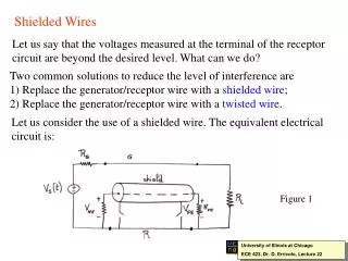
Additional Suggestions to Improve Isolation • Vast Majority of leakage problems occurred because the lid did not make a flush contact to the edges of the wall. • A cross section of a possible solution is shown in the upper right • The lid and the wall interlock with each other in addition to being padded with gasket material • The JRE 1618 shown here implements this solution • Latches should also be used to fasten the lid down on the box • Another source of poor isolation was the USB cable. • The USB cable was picking up the transmitted signal and acting as an antenna outside the box • A USB filter can be used, but performance usually deteriorates after 1 GHz • Thus, the outside shield of the cable must somehow be completely grounded to the box