Download
1 / 1
10 likes | 120 Views
Uniform Circular Motion Apparatus. 2. 5. Dr. Zengqiang Liu , Jing Chen, Shunjie Yong, Steve Zinsli. 1. 3. 6. Saint Cloud State University, St. Cloud, MN 56301. 8. 4. 9. 7. 1. Magnet 2. Power supply 3. Accelerometer 4. POV display

E N D
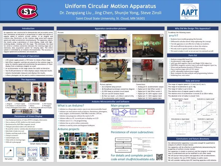
Uniform Circular Motion Apparatus 2 5 Dr. Zengqiang Liu , Jing Chen, Shunjie Yong, Steve Zinsli 1 3 6 Saint Cloud State University, St. Cloud, MN 56301 8 4 9 7 1. Magnet 2. Power supply 3. Accelerometer 4. POV display 5. 9V battery 6. microcontroller 7. Motor 8. Photogate 9. Pasco Photogate Smart timer 10. Rotating beam with dual display Introduction Why Did We Design This Apparatus? Apparatus construction pictures An apparatus was constructed to demonstrate and accurately prove that centripetal acceleration is proportional to radius and square of angular speed in uniform circular motion, in an elegant and creative way. Electronics on the rotation stage sense both angular speed and radial acceleration simultaneously. The apparatus reports the results using a persistence of vision display, made with light-emitting diodes, rotating with the stage. This eliminates the need for wired or wireless connection between the rotating stage and a stationary data acquisition system for relaying data. The entire system is controlled by an Arduino microcontroller. The accuracy in angular speed and acceleration are around 2%. To address the following issues: Pictures 10 (A) (C) (E) a=w2r? • Students have trouble grasping this formula • Differential calculus doesn’t help explaining the concept. • Our lab apparatus is not effective to help our students. • We need sufficient data points to show this relation. • We only want to spend a small amount of money. • We want to make it cool, so we can use it in outreach as well Parts list Principle of Operation A DC power supply powers a 15V motor to rotate a Pasco stage. Hall-Effect magnetic switches are placed on the rotation stage to sense itsrotation speed and synchronize the persistence of vision display from a stationary magnet on a poll. An accelerometer on the stage senses the radial acceleration. Two 8-LEDpersistence of vision displays output measured results. Arduino (homemade) measures and displays the results. A Pasco photogate can be used to confirm measurement accuracy. • Arduino compatible board $13 • Accelerometer (±18g range) $18 • 74HC595 shift registers (2pcs) and Bright LEDs (16pcs) $2 • Hall Effect magnetic sensors (2pcs) and small magnets (2pcs) $4 • Wires and perforation boards or PCBs $4-$12 • Pasco rotation stage with 15V DC motor • 15VDC adjustable student power supply • Basic computer for data analysis and programming Arduino • Soldering iron, wire cutter (D) (F) (B) The Apparatus Data and error The range of angular speed is 1.2 rev/s to 4.2 rev/s. The range of acceleration is up to 18g. The range of radius is up to 22cm. The relative error of angular speed is within 2%. The relative error of acceleration is around 2% at 20cm radius. The absolute error of radius is around 1mm. Picture captions: (A) Complete setup picture (B) Breadboardprototype connection diagram (C) POV head on printed circuit board (D) Low-costDIY Arduino board (E) Test run result: w=2.34rev/s and a=4.47g (F) Accelerometer and L-bracket Connections: Analog pin 0: accelerometer output Digital pin 8: Hall Effect switch 1 Digital pin 9: Hall Effect switch 2 Digital pin 10: Shift register clock Digital pin 11: Shift register latch Digital pin 12: Shift register data Arduino Microcontroller and Software What is an Arduino? Main program • Arduino is a cheap open-source, easy to use microcontroller board • Arduino can read sensors such as buttons, thermistors, photogates, sonic rangers, accelerometers, Hall Effect switches, GPS etc. • Arduino runs programs without the need of a PC • Arduino talks to a PC via serial port or displays on LCD • Arduino uses C/C++ for programming • Arduino has an active online community • Arduino is used by artists and beginner hobbyists Persistence of Vision Display if ((btn_1.sense()==buttons_down)||(btn_2.sense()==buttons_down)){ this_trigger=millis(); period=this_trigger-last_trigger; last_trigger=this_trigger; if (period>1000) period=100; // This prevents the display from stuck at a low speed. w=1000/(float)(period)/2; abs_level=analogRead(ay_pin); y_level=abs_level-ay_base; a_g=((float)y_level)/gy_factor; if (millis()<30000) sprintf(msg,“ AAPT Omaha 2011"); else sprintf(msg," %1d.%02d RPS %2d.%02dg", int(w), int((w-int(w))*100), int(a_g), int((a_g-int(a_g))*100)); displayMsg(msg,int(2000/w),1);} • Uses human persistence of vision (POV) to display information • Uses a column of LED, similar to a dot-matrix printer • Synchronized by Hall Effect magnetic switch • Only gets persistence above 2Hz refresh rate • No need for wired or wireless data download or transfer • Kids think it looks very cool • Displays anything made of dots • Cheapto construct • Limited display area • Only works on rotating stages • Difficult to photograph Arduino projects Persistence of vision subroutines Conclusions and future directions Our demonstration apparatus is accurate enough for quantitative analysis of uniform circular motion. Our apparatus will be effective in qualitatively demonstrating the properties of uniform circular motion. Our apparatus is simple to construct and the program is relatively easy to understand and can be modified to suit other needs. We will pursue more projects and apparatus with accelerometers. We will explore the use of POV displays in public reach. We will consider making more DIY teaching apparatus with Arduino. void displayMsg(char msg[], unsigned int delayus, unsigned char spacing){ char i=0; while (msg[i]){ displayChar(msg[i],delayus); updateLed(0); delayMicroseconds(delayus); i++;}} void displayChar(unsigned char ch, unsigned intdelayus){ for (char i=0;i<5;i++){ updateLed(font[ch-32][i]); delayMicroseconds(delayus);}} void updateLed(unsigned char first8) { digitalWrite(myLatchPin, LOW); shiftOut(myDataPin, myClockPin, LSBFIRST, first8); digitalWrite(myLatchPin, HIGH);} Sample display message For details and complete project code email zliu@stcloudstate.edu Magnet on a poll Dot-matrix printer output POV display head Hall probe Google.com