Download
1 / 51
560 likes | 784 Views
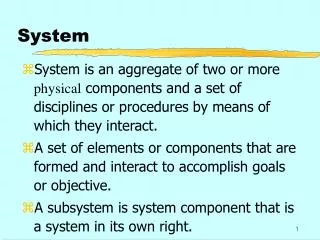
TELECOMMAND SYSTEM. Data Management Service. Data Routing Service. Channel Service. Application Process Layer. TC Packet. TC Frame. Command Directive. Segmentation Layer. Coding Layer. System Management Layer. TC Segment. CLTU. TC Application Data. Transfer Layer. Physical Layer.

E N D
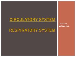
TELECOMMANDSYSTEM by Sisto Maurizio
Data Management Service Data Routing Service Channel Service Application Process Layer TC Packet TC Frame Command Directive Segmentation Layer Coding Layer System Management Layer TC Segment CLTU TC Application Data Transfer Layer Physical Layer Packetization Layer Physical Waveform TELECOMMANDING ARCHITECTURE by Sisto Maurizio
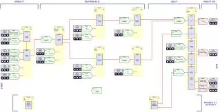
6 bytes Up to 65536 bytes TC Packet PKT HDR USER DATA 1 byte Up to 1018 bytes ... TC Segment SEG HDR SEG HDR 5 bytes Up to 1019 bytes TC Frame FRM HDR K bits K bits K bits ... TC Codeblock CB 1 CB 2 CB N CLTU ST SEQ TAIL SEQ TELECOMMAND DATA STRUCTURES by Sisto Maurizio
CHANNEL SERVICE PHYSICAL LAYER by Sisto Maurizio
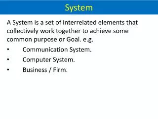
SENDING END SERVICE SPECIFICATION • Inputs from the layer above: • Buffer of bits corresponding to a CLTU and control information. • Outputs to the layer above: • Status of the physical telecommand channel. • Outputs to the receiving end of the layer: • Modulated radio frequency waveforms. • Internal functions: • Establishes the physical radio frequency path to the spacecraft. • Radiates a buffer of data bits serially according to the PLOP requested by the layer above. by Sisto Maurizio
RECEIVING END SERVICE SPECIFICATION • Inputs from the sending end of the layer: • Modulated radio frequency waveforms which have been radiated by a transmitting station. • Outputs to the layer above: • Synchronized detected “dirty” symbol stream and status of the RF lock. • Modulated carrier/subcarrier presence, used by layer above to select between Inactive and Search states. • Internal functions: • Receives and detects the modulated carrier/subcarrier. • Performs demodulation and symbol synchronization. • Determines the state (Active/Inactive) of the physical TC channel. • Performs symbol detection. • Informs the layer above of status of the Physical layer. by Sisto Maurizio
STANDARD DATA STRUCTURES • Acquisition Sequence: • The preferred minimum length is 16 bytes. • It shall be alternating “1” and “0”, starting with either a “1” or a “0”. • CLTU: • Each codeblock within the CLTU provides at least 2 data transitions. • If it required more frequent transitions, the CLTU must have been randomised as described in the Coding Layer. • Idle Sequence: • It provides for maintenance of symbol synchronization in the absence of CLTUs. • It is a sequence of alternating “1” and “0”. • The length is an unconstrained number of bits. by Sisto Maurizio
STANDARD PROCEDURES • Carrier Modulation Modes (CMM): • CMM-1: unmodulated carrier only. • CMM-2: carrier modulated with Acquisition Sequence. • CMM-3: carrier modulated with TC data. • CMM-4: carrier modulated with Idle Sequence. • Physical Layer Operations Procedures (PLOPs) PLOP-1: • It is a procedure for individually radiating CLTUs. • Decoder is always forced into the Inactive state by deactivating the physical TC channel after the end of transmission of each CLTU. • Physical Layer Operations Procedures (PLOPs) PLOP-2: • Decoder is in the Search state after each CLTU (channel not deactivated). • Decoder is forced into the Inactive state only at the end of transmission of a series of CLTUs. • It is recommended insert a minimum Idle Sequence of one byte between each CLTU. by Sisto Maurizio
CHANNEL SERVICE CODING LAYER by Sisto Maurizio
SENDING END SERVICE SPECIFICATION • Inputs from the layer above: • “Input Data” to be included in a single CLTU and control instructions. • Inputs from the layer below: • Status of the physical TC channel. • Outputs to the layer above: • Status of the physical TC channel. • Outputs to the layer below: • CLTUs and control instructions. • Internal functions: • Conditions Input TC Data by randomising it if used by a mission. • Adds fill as necessary to complete the last codeblock of the CLTU. • Encodes the Input TC Data (TC Frames) into TC Codeblocks. • Forms the TC Codeblocks into a CLTU by adding the Start and Tail Sequence. by Sisto Maurizio
RECEIVING END SERVICE SPECIFICATION • Outputs to the layer above: • “Clean” decoded and derandomised (if used) TC data from each codeblock which have passed the decoder quality check. • Decode Status (indicating start, continuity, end of data), control information. • Inputs from the layer below: • Synchronized detected dirty symbol stream, control information and status. • Internal functions: • Detects the CLTU Start Sequence: subsequent codeblock are automatically synchronized by being contiguous. • Makes an estimate to determine if an error has probably occurred. • Optionally makes an estimate of the correct value and continues decoding. • If a detected or uncorrectable error is encountered, leaves the Decode state and enters the Search state: signals the stop of valid TC data. • If modulation is lost, leaves the Decode state and enters the Inactive state. • The valid TC data is derandomised (if used) before passing to the layer above. by Sisto Maurizio
Information (k bits) Error control (8 bits) (1) (2.1) (2.2) TC CODEBLOCK FORMAT (1) Information (k bits): • Contains “k” information bits (k=32,40,48, or 56 bits): it shall be fixed. • Information bits may be randomised. • The preferred overall length “n” of the TC Codeblock is 64 bits (k=56bits). (2.1) Parity Check Bits (7 bits): • The encoding procedure for generating these parity bits is described later. (2.2) Appended Filler Bit (1 bit): • Provide an overall Codeblock length which is an integer number of byte. • This Filler Bit shall always be a zero. by Sisto Maurizio
Start Sequence Encoded TC Data Tail Sequence (1) (2) (3) CLTU FORMAT (1) Start Sequence (16 bits): • Pattern with low autocorrelation sidelobes: 1110101110010000 (2) Encoded TC Data: • Consists of a set of TC Codeblocks. (3) Tail Sequence: • It shall have the same length as the TC Codeblocks that are being used. • It is constructed specifically to be a noncorrectable sequence. • It shall consist of leading octets having the pattern: 11000101 • The last octet completes the tail sequence field, and always has the pattern: 01111001 by Sisto Maurizio
INPUT DATA RANDOMIZED INPUT DATA X8 X7 X6 X5 X4 X3 X2 X1 RANDOMISATION PROCEDURE • Used if a sufficient bit transition density is not ensured for the channel. • Random sequence shall be generated using the following polynomial: • h(x)=x8+x6+x4+x3+x2+x+1 (it repeats after 255 bits) • The BTG (Bit Transition Generator) is pre-set to the “all-ones” state: • It remains in this state until Start Sequence has been detected. • It is reset in this state following a failure of the decoder. • Derandomisation is applied to the successfully decoded TC data. • Adders are Modulo-2 (EX-OR). by Sisto Maurizio
ENCODING/DECODING PROCEDURE (1) • The code used is a (63,56) modified BCH: • The generator polynomial is: g(x)=x7+x6+x2+1 • The same encoding also serves for shortened cases (k=32,40,48) by forcing to zero the other (56-k) bits (“virtual fill”: not outputted, nor transmitted). • If the Input Data do not fit exactly within an integral number of Codeblocks, last octets of the information field may contain “Fill” bits (a sequence of alternating “ones” and “zeros” starting with a “zero”). • Codeblocks may be decoded using the following mode: • Error-detecting mode (TED mode): one, two or three bits in error will be detected. • Error-correcting mode (SEC mode): one bit in error will be corrected and two bits in error will be detected. by Sisto Maurizio
INFORMATION BITS CODED DATA OUTPUT (1) (1) (2) (3) (2) ZERO (3) ZERO P5 P2 P4 P3 P1 P6 P0 X0 X1 X2 X3 X4 X5 X6 ENCODING/DECODING PROCEDURE (2) • The shift registers are initialized to “zero”. • The switches are: • In position (1), while the “k” TC data bits are being transmitted. • In position (2), for the seven parity bits. • In position (3), for the appended fill bit. by Sisto Maurizio
DATA ROUTING SERVICE TRANSFER LAYER by Sisto Maurizio
SENDING END SERVICE SPECIFICATION (1) • Inputs from the layer above: • TC Segments and control information. • Inputs from the receiving end of the layer: • Information about the status of receipt of TC Frames using CLCW (Command Link Control Word). • Inputs from the layer below: • Status of the physical layer. • Outputs to the layer above: • Status of the data routing process and availability of VCs. • Outputs to the receiving end of the layer: • “Control Command” TC Frames, which instruct the receiving end. • Outputs to the layer below: • Buffer of TC data bits and control instructions. by Sisto Maurizio
SENDING END SERVICE SPECIFICATION (2) • Internal functions: • Encapsulates TC Segments into TC Frames. • Translates control instructions received from the layer above into the appropriate set of operational procedures. • Creates Control Command TC Frames to control the FARM (Frame Acceptance and Reporting Mechanism). • Supervises the transfer of TC Frames by executing a FOP (Frame Operation Procedure). • Retransmits TC Frames as required to rectify channel-induced errors. by Sisto Maurizio
RECEIVING END SERVICE SPECIFICATION (1) • Inputs from the layer above: • Information defining the ability of the layer above to accept more data. • Inputs from the sending end of the layer: • Control Command TC Frames. • Inputs from the layer below: • “Clean” octets of decoded TC data (only correct data). • Indication of the start of the first valid octet of TC data (“Data Start” signal). • Indication of the last valid octet of TC data (“Data Stop” signal). • Control information describing the status of physical channel. • Outputs to the layer above: • TC Segments which have been extracted from TC Frames. • Outputs to the sending end of the layer: • CLCWs used by the FOP to control the transmission or retransmission of TC Frames. by Sisto Maurizio
RECEIVING END SERVICE SPECIFICATION (2) • Internal functions: • Responds to Control Command TC Frames received from the sending end. • Performs the “Frame Validation Check Procedure” for all TC Frames and the “Frame Acceptance and Reporting Mechanism” for Type-A Frames. • Creates reports (CLCWs) to the sending end describing the status of TC Frame acceptance. • Processes TC Frame which have been retransmitted as required to rectify channel-induced errors. • Extracts TC Segments and passes them to the layer above. by Sisto Maurizio
PWRX V(R)+PWRX-1 V(R) 256-WRX V(R)-NWRX NWRX COMMAND OPERATION PROCEDURE (COP) • A COP consists of a pair of synchronised procedures: FOP and FARM. • COP-1 is a closed-loop TC protocol that uses “go-back-n” techniques. • COP-1 provides two services: • Sequence-Controlled Service: used for Type “AD” and “BC” Frames. • Expedited Service: used only for Type “BD” Frames. • 1 WTX PWRX and WTX < 256 • 2 WRX 254: always even integer • PWRX = NWRX = WRX/2 • V(R): FARM counter by Sisto Maurizio
Frame header (5 bytes) Data field Error control (1.1) (1.2) (1.3) (1.4) (1.5) (1.6) (1.7) (1.8) (2) (3) TC FRAME FORMAT (1) (1.1) Version Number (2 bits): • At present, only Version-1 is defined: the bits are set to value “00”. (1.2) Bypass Flag (1 bit): • “0” = Type-A TC Frame (normal frame acceptance checks of the FARM). • “1” = Type-B TC Frame (normal frame acceptance checks are bypassed). (1.3) Control Command Flag (1 bit): • “0”=Data Frame (mode “D”); “1”=Control Command Frame (mode “C”). (1.4) Reserved Spares (2 bits): • At present shall be set to value “00”. (1.5) Spacecraft Identifier (10 bits) (1.6) Virtual Channel Identifier (6 bits): • Provides 64 VC: each VC has its own CLCW reporting. by Sisto Maurizio
TC FRAME FORMAT (2) (1.7) Frame Length (10 bits): • Contains the length “C”, in byte, between the first bit of the Frame Header and the last bit of the Error Control Field, expressed as: C = (n°byte - 1) (1.8) Frame Sequence Number “N(S)” (8 bits): • It is an up-counting modulo-256 binary number used to check the sequentially of Type-A TC Frames; in Type-B Frames it shall be “all zeros”. (2) Frame Data Field (variable but integer number of bytes): • Length up to 1019 bytes (1017 bytes if Error Control Field is used). • Contains: Control Command (only UNLOCK and SET V(R)) or Data Unit. (3) Frame Error Control Field (optional 16 bits): • Systematic binary (n,n-16) block code with polynomial: g(x)=x16+x12+x5+1 • Encoding: the shift registers are initialized to “1”. (n-16) bits enter with A and B closed, and C open. Other 16clock with A=“0”, B open, C closed. • Decoding: the shift registers are initialized to “1”. n bits enter: (n-16) bits with B open and 16 bits with B closed. by Sisto Maurizio
ZERO A C OUTPUT INPUT B B INPUT OUTPUT ENCODER AND DECODER Encoder Decoder by Sisto Maurizio
PERFORMANCE NOTES Frame rejection performance • Required: 10-3 Undetected error performance • Required: 10-9 Binary Symmetric Channel (BSC) with AWGN is assumed. • A=TED mode; B=SEC mode • p = 10-5 is assumed • N = 1 40 • PFA=PSA+(1-PSA)PCA where: PSA=1-(1-p)16 PCA=1-[(1-p)n]N • SEC Mode (BCH code only): PUE = 10-10 10-9 • PFB=PSB+(1-PSB)PCB where: PSB=1-[(1-p)16+16p(1-p)15] PCB=1-[(1-p)n+np(1-p)n-1]N • TED Mode (BCH code only): PUE = 10-16 10-15 • p = channel bit error rate • n = n° of bits in Codeblock • N = n° of Codeblocks into Frame • SEC Mode (BCH + CRC frame): PUE = 10-21 10-19 by Sisto Maurizio
First fields (16 bits) Flags (5bits) Last field (11 bits) (1.1) (1.2) (1.3) (1.4) (1.5) (1.6) (2) (3.1) (3.2) (3.3) CLCW FORMAT (1) (1.1) Control Word Type (1 bit): • Always “0” for a CLCW. (1.2) CLCW Version Number (2 bits): • At present, only Version-1 is defined: the bits are set to value “00”. (1.3) Status Field (3 bits): • Free: it may be used by Agencies for enhancements to TC operations. (1.4) COP In Effect (2 bits): • At present, only COP-1 is defined: the bits are set to value “01”. (1.5) Virtual Channel Identifier (6 bits): • Provides 64 VC: each VC has its own CLCW reporting. (1.6) Reserved Spares (2 bits): • At present shall be set to value “00”. by Sisto Maurizio
CLCW FORMAT (2) (2) Flags (5 bits): • No RF Available: “1” = physical channel not available. • No Bit Lock: “1” = no bit lock achieved. • Lockout: “1” = FARM in lockout state (all Type-A Frames are rejected). • Wait: “1” = unable to pass Type-A Frames to the Segmentation layer. • Retransmit: “1” = one or more Type-A Frames, on a particular VC, have been rejected or found missing by the FARM. (3.1) FARM-B Counter (2 bits): • Increments once each time a Type-B Frame is accepted on a VC. (3.2) Reserved Spare (1 bit): • At present shall be set to value “0”. (3.3) Report Value “N(R)” (8 bits): • Contains next expected frame sequence number V(R) (FARM counter): used only for Type-A Frame. by Sisto Maurizio
DATA ROUTING SERVICE SEGMENTATION LAYER by Sisto Maurizio
SENDING END SERVICE SPECIFICATION • Inputs from the layer above: • TC Packets and control instructions. • Inputs from the layer below: • Information describing the status of transfer of Frame through a given VC. • Outputs to the layer above: • Information describing the status of transfer of TC Packets. • Outputs to the layer below: • TC Segments and control instructions. • Internal functions: • Assigns individual TC Packets to particular MAPs. • Breaks or aggregates the TC Packets into pieces (data field of Segment). • Optionally labels each piece with sequence control and MAP id. • Multiplexes TC Segments from different MAPs together onto one VC. • Monitors the process of transferring and knows status and availability of each VC. by Sisto Maurizio
RECEIVING END SERVICE SPECIFICATION • Inputs from the layer above: • Information concerning the ability of the higher layer to accept more data. • Inputs from the layer below: • TC Segments in sequence and complete, without omission or duplication. • Outputs to the layer above: • Reconstructed TC Packets. • Outputs to the layer below: • Information concerning the ability of this layer to accept more data. • Internal functions: • Receives TC Segments from the Transfer layer, delivered on individual VC. • Sorts Segments associated with individual VCs according to their MAP id. • Determines when all TC Segments associated with a particular TC Packet have been received correctly. • Extracts and reconstructs TC Packets; passes them to the layer above. by Sisto Maurizio
Segment header (1byte) Segment data field (up to 1018 bytes) (1.1) (1.2) (2) TC SEGMENT FORMAT (1.1) Sequence Flags (2 bits): 0 1: First Segment of TC Packet on one MAP. 0 0: Continuing Segment of TC Packet on one MAP. 1 0: Last Segment of TC Packet on one MAP. 1 1: No segmentation. (1.2) Multiplexer Access Point (MAP) Identifier (6 bits): • This six-bit field enables up to 64 MAP addresses to be associated with each VC provided by Transfer layer. • The MAP facility allows user command data from different sources to be multiplexed together so that they share the communications capacity of one VC (no resource monopoly). (2) Segment Data Field (up to 1018 bytes): • Contains all or a portion or an aggregation of TC Packets. by Sisto Maurizio
DATA MANAGEMENT SERVICE PACKETIZATION LAYER by Sisto Maurizio
SENDING END SERVICE SPECIFICATION (1) • Inputs from the layer above: • Named sets of transportable TC Application Data and control instructions. • Requests for reports of the status of data and for security measures. • Inputs from the receiving end of the layer: • TLM Packets describing the status of receipt of TC Packets. • Inputs from the layer below: • Reports describing the status of the data routing process. • Outputs to the layer above: • On-demand reports defining the transport status of TC Application Data. • Outputs to the receiving end of the layer: • Control instructions defining the data reassembly and forwarding procedures which are to be used, including parameters for algorithms which implement optional data security measures. • Outputs to the layer below: • TC Packets, including security encoding of this data and control instructions. by Sisto Maurizio
SENDING END SERVICE SPECIFICATION (2) • Internal functions: • Encapsulates named sets of TC Application Data into the data field of TC Packets, adding the header of TC Packets. • Inserts local naming syntax into the TC Packets to maintains traceability. • Encodes the Application Data as required to implement data security measures. • Generates control instructions to the layer below and to the receiving end. • Analyses reports from the receiving end and from the layer below. • Generates on-demand reports to the layer above describing the status of end-to-end transport of named sets of telecommands. by Sisto Maurizio
RECEIVING END SERVICE SPECIFICATION (1) • Inputs from the layer above: • Information concerning the ability of the layer to accept more data. • Inputs from the sending end of the layer: • Control instructions defining system conditions which must exist in order to reassemble and pass the data to the layer above, including security measures. • Inputs from the layer below: • TC Packets and information describing the status of the data routing process. • Outputs to the layer above: • Named sets of TC Application Data and transport status information relating to the correctness, completeness and sequentially of the TC data. by Sisto Maurizio
RECEIVING END SERVICE SPECIFICATION (2) • Outputs to the sending end of the layer: • Reports describing the status of receipt of TC Packets. • Outputs to the layer below: • Reports describing the ability of the layer to accept more data. • Internal functions: • Extracts TC Application Data from the data fields TC Packets. • Analyses control instructions from the sending end. • Passes the TC Application Data to the layer above. • Formulates reports to the sending end describing the status of receipt and reassembly of particular named sets of TC Application Data. • Formulates reports to the layer below describing its ability to accept more data. by Sisto Maurizio
Secondary header Primary header (6 bytes) Application data (1.1) (1.2) (1.3) (1.4) (1.5) (1.6) (1.7) (2) (3) TC PACKET FORMAT (1) (1.1) Version Number (3 bits): • At present, only Version-1 is defined: the bits are set to value “000”. (1.2) Type (1 bit): • “0” = Telemetry Packet; “1” = Telecommand Packet. (1.3) Secondary Header Flag (1 bit): • Absence (“0”) or presence (“1”) of a Secondary Header within TC Packet. (1.4) Application Process Identifier (11 bits): • Identifies the individual receiving application process in the spacecraft. (1.5) Sequence Flags (2 bits): 0 1: First Packet of TC Application Data. 0 0: Continuing Packet of TC Application Data. 1 0: Last Packet of TC Application Data. by Sisto Maurizio
TC PACKET FORMAT (2) (1.6) Packet Name or Sequence Count (14 bits): • If the Packet is independent of other spacecraft, naming consists of sequence number; otherwise it may be internally partitioned to include the File Name. (1.7) Packet Length (2 bytes): • Contains the length “C”, in byte, between the first bit of the Secondary Header and the last bit of the Packet, expressed as: C = (n°byte - 1) (2) Secondary Header (optional and variable but integer number of bytes): • Provides a means for encoding any auxiliary data (at present not defined). (3) Application Data (variable): • Users are free to adopt whatever formatting conventions are convenient. • An error detection code may be included in this field to verify the overall integrity of the TC Packet. • Secondary Header Length + Application Data Length = up to 65536 bytes. 1 1: Standalone Packet. by Sisto Maurizio
SECURITY MEASURES • Data protection may be provided by two mechanisms: • Physical: impracticable in space mission. • Logical: manipulation or interpretation data is extremely difficult. • A system, with logical mechanism, may use first technique only or both techniques together: • Encrypted Authentication: the sending end generates a unique authentication word accompanies each clear-text block that is transmitted. The receiving end recognises the authentication word by performing complementary decryption, and send back a status message in clear-text to the sending end. • Data Encryption: the command application data are transformed to make them unintelligible to an unauthorised observer. TC Application Data are transformed by applying special algorithms and can only be interpreted after processing by a complementary process at the receiving end. by Sisto Maurizio
DATA MANAGEMENT SERVICE SYSTEM MANAGEMENT LAYER by Sisto Maurizio
SENDING END SERVICE SPECIFICATION (1) • Inputs from the layer above: • Command Directives and their delivery control instructions. • Requests for reports of delivery status. • Inputs from the receiving end of the layer: • Reports defining the status of receipt of commands. • Inputs from the layer below: • Reports defining the status of end-to-end transport of named sets of TC. • Outputs to the layer above: • Reports describing the delivery status of Command Directives. • Outputs to the receiving end of the layer: • Control instructions defining conditions which must exist at time of delivery. • Outputs to the layer below: • Named sets of TC Application Data and control instructions. • Requests for the status of transport of TC Application Data. • Requests to implement security measures. by Sisto Maurizio
SENDING END SERVICE SPECIFICATION (2) • Internal functions: • Translates abstract-syntax user Command Directives into correspondingly transportable concrete-syntax TC Application Data. • Prepares TC Application Data for transport, including security measures. • Establishes the TC Sessions by requesting physical connection services from lower layers, and passing the TC Application Data to the layer below. • Manages and supervises the TC Sessions (e.g., by permitting TC Application Data to be suspended, resumed, released for delivery and aborted as required). • Generates control instructions to the receiving end. • Analyses reports from the layer below which describe the status of transport of TC Application Data and creates appropriate recovery instructions. • Formulates on-demand reports to the layer above which describe the delivery status of TC Application Data. by Sisto Maurizio
RECEIVING END SERVICE SPECIFICATION (1) • Inputs from the layer above: • Information concerning the ability of the layer to accept more data. • Inputs from the sending end of the layer: • Session control instructions. • Inputs from the layer below: • TC Application Data and transport information relating to the correctness, completeness and sequentially of the received TC Application Data. • Outputs to the layer above: • User Command Directives. • Outputs to the sending end of the layer: • Reports defining the status of delivery of commands. • Outputs to the layer below: • Reports defining the ability of the layer to accept more data. by Sisto Maurizio
RECEIVING END SERVICE SPECIFICATION (2) • Internal functions: • Receives TC Application Data from the layer below. • Receives control instructions from the sending end of the layer defining the conditions for delivery of TC Application Data to the layer above. • Receives transport status information from the layer below and determines when the TC Application Data are ready for delivery to the layer above. • Translates concrete-syntax TC Application Data back into abstract-syntax commands, if required by the layer above. • Delivers user Command Directives to appropriate addresses within the layer above when the delivery conditions are satisfied. • Formulates reports back to the sending end of the layer describing the delivery status of user commands. • Formulates reports to the layer below describing its ability to accept more data. by Sisto Maurizio
DATA MANAGEMENT SERVICE APPLICATION PROCESS LAYER by Sisto Maurizio
SENDING END SERVICE SPECIFICATION (1) • Inputs from the user: • Individual requests for specific command actions (in high-level language). • Instructions defining the delivery and execution requirements. • Inputs from the receiving end of the layer: • Reports describing command execution status. • Inputs from the layer below: • Reports describing TC system delivery performance. • Outputs to the user: • Mission information and reports about execution of specific command actions. • Reports status delivery and naming convention used to label the commands. • Outputs to the receiving end of the layer: • Control instructions defining conditions which must exist at time of execution. • Outputs to the layer below: • Multi-user Command Directives and requests for their status of delivery. • Control instructions which select the particular system configuration. by Sisto Maurizio
SENDING END SERVICE SPECIFICATION (2) • Internal functions: • Maintains a data base of mission information. • Displays selected information in response to queries from individual users. • Iteratively responds to user requests by indicating system resource availability. • Translates user requests into correspondingly Command Directives. • Provides facilities for the user to suspend, resume or abort the transfer of Command Directives at any time prior to execution. • Integrates the command directives from multiple users into named sets and communicates the naming conventions to the user. • Organises the named sets of directive into TC Sessions and possibly estimates the overall effect of TC Sessions by simulating the response to commands. • Generates the control instructions to the layer below. • Generates the control instructions to the receiving end. • Analyses reports from the receiving end and from the layer below and formulates on-demand reports to the user. by Sisto Maurizio
RECEIVING END SERVICE SPECIFICATION (1) • Inputs from the spacecraft system: • Current spacecraft state, resource status, time. • Inputs from the sending end of the layer: • Control instructions defining conditions which must exist in order to execute the named sets of Command Directives. • Inputs from the layer below: • Named sets of Command Directives. • Outputs to the spacecraft system: • Executed command actions which cause changes in spacecraft state. • Outputs to the sending end of the layer: • Reports describing command execution status. • Outputs to the layer below: • Reports describing ability of the layer to accept more data. by Sisto Maurizio
RECEIVING END SERVICE SPECIFICATION (2) • Internal functions: • Receives named sets of executable commands. • Analyses control instructions from the sending end which define the operational conditions that must exist at time of execution. • Execute named sets of commands when operational conditions are satisfied. • Provides the capability for the user to suspend, resume or abort named sets of command execution. • Formulates reports to the sending end describing the status of command execution. • Notifies the layer below its capability to accept more data. by Sisto Maurizio