Download
1 / 81
830 likes | 1.21k Views
CCGT Operations Principles. Process Control. Process Control – Lesson Objectives. Understand some of the parameters which need to be measured in the power station environment Describe methods of measuring pressure, temperature, level and flow

E N D
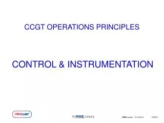
CCGT Operations Principles Process Control
Process Control – Lesson Objectives • Understand some of the parameters which need to be measured in the power station environment • Describe methods of measuring pressure, temperature, level and flow • Explain methods of transmitting information to the control system • Describe the principle of a control system • Examine examples of control configurations • Explain the configurations of hardware used to implement control systems
Battersea Power Station – “Engineer” Synchronising for the morning peak!
Agecroft P.S. Unit Control Room – Design Circa -1960’s (photo probably 1980’s)
Field Instruments • Pressure Measurement • Level Measurement • Flow Measurement • Temperature Measurement
Manometer Principle • Pressure due to a head of water = DENSITY x GRAVITY x HEIGHT = Kg/m³ x m/sec² x M = N/M²
Bourdon Gauge - Movement This measure principle can be adapted for remote reading by connecting the measuring element to a transducer such as an LVDT – Linear Variable Differential Transformer
Closed Tank Measurement with Constant Head Chamber – e.g. condenser or boiler drum
Constant Head Steam 0 mm Water L H Boiler Drum Measurement – Constant Head
Drum Level Measurement • Accuracy due to density of fluid in “wet legs” (reference leg and measured leg) • Caused by effects of drum pressure at different loads • Caused by difference in temperature between measuring device and fluids in drum
Drum Pressure Transmitter Constant Head Chamber Drum centre line 0 mm Reference Leg Force on measuring element is equal to height difference Drum level Transmitter Drum Density Compensation Traditional UK method – Pressure Transmitter Corrected signal is used in three element control scheme Density is inferred from pressure measurement and is used to electronically correct the level signal
Drum Density Compensation - Development - Devices such as the IMV 31 shown here can process the information from thermocouples installed on the “legs” and compensate for density differences with “on-board processor
Drum Steam Connection DISPLAY UNIT Electrodes DETECTOR AND LOGIC UNIT Hydrastep Vessel Electrode Drum Water Connection Electrical connection to Detector Ceramic Insulator ElectrodeTip Hydrastep Vessel Hydrastep - Components
Quantity Measurement • There are two different types of “quantity meter, inferential and positive displacement meters • The principle of operation of a positive displacement “quantity” meter is that a known volume is passed from the inlet to the outlet of the meter • The principle of operation of an inferential quantity meter is that the quantity is inferred by measuring the velocity
Venturi Principles • The principle of operation of an inferential quantity meter (1)is that the quantity is inferred by measuring the velocity • Therefore by measuring the difference in pressure across the orifice plate, the rate of flow can be calculated • Rate of flow is proportional to the square root of the differential pressure (head)
Flow Measurement – Differential Producers – Orifice Plate and Flow Nozzle
Flow Measurement - Electromagnetic Principle of Operation<>The operation of a magnetic flowmeter or mag meter is based upon Faraday's Law, which states that the voltage induced across any conductor as it moves at right angles through a magnetic field is proportional to the velocity of that conductor.Faraday's Formula:E is proportional to V x B x D where:E = The voltage generated in a conductorV = The velocity of the conductorB = The magnetic field strengthD = The length of the conductor
Ultrasonic Flow Metering Insertion Technology Clamp On Technology
Thermocouples Temperature measurements based on the use of a thermocouple rely on the basic principle that: If two dissimilar metals are connected at one end to form a measuring (hot) junction and are connected to a temperature indicator at the other end to form a reference (cold) junction, a voltage is produced at the measuring instrument which is determined by the temperature difference between the two junctions. (Thermoelectric effect)