Download
1 / 15
150 likes | 290 Views
Unit 11 Latches and Flip-Flops. Ku-Yaw Chang canseco@mail.dyu.edu.tw Assistant Professor, Department of Computer Science and Information Engineering Da-Yeh University. Outline. 11.1 Introduction 11.2 Set-Reset Latch 11.3 Gated D Latch 11.4 Edge-Triggered D Flip-Flop 11.5 S-R Flip-Flop

E N D
Unit 11Latches and Flip-Flops Ku-Yaw Chang canseco@mail.dyu.edu.tw Assistant Professor, Department of Computer Science and Information Engineering Da-Yeh University
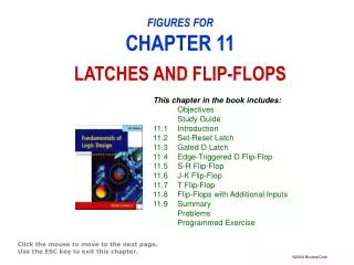
Outline 11.1 Introduction 11.2 Set-Reset Latch 11.3 Gated D Latch 11.4 Edge-Triggered D Flip-Flop 11.5 S-R Flip-Flop 11.6 J-K Flip-Flop 11.7 T Flip-Flop 11.8 Flip-Flops with Additional Inputs 11.9 Summary Latches and Flip-flops
Gated D Latch • Two inputs • A data input (D) • A gate input (G) • Constructed from an S-R latch and gates Latches and Flip-flops
Timing Diagram • G = 1 • The Q output follows the D input. • Transparent latch • G = 0 • The Q output holds the last value of D (no state change) Latches and Flip-flops
Symbol and Truth Table Latches and Flip-flops
Outline 11.1 Introduction 11.2 Set-Reset Latch 11.3 Gated D Latch 11.4 Edge-Triggered D Flip-Flop 11.5 S-R Flip-Flop 11.6 J-K Flip-Flop 11.7 T Flip-Flop 11.8 Flip-Flops with Additional Inputs 11.9 Summary Latches and Flip-flops
D Flip-Flop • Two inputs • D (data) • The output changes only in response to the clock, not to a change in D. • Ck (clock) Latches and Flip-flops
D Flip-Flop • The output can change in response to a 0 to 1 transition on the clock input • Triggered on the rising edge (or positive edge) • The output can change in response to a 1 to 0 transition on the clock input • Triggered on the falling edge (or negative edge) • Active edge • The clock edge (rising or falling) that triggers the flip-flop Latches and Flip-flops
D Flip-Flop • The state after the active clock edge (Q+) is equal to the input (D) before the active edge. • Characteristic equation : Q+ = D Latches and Flip-flops
D Flip-Flop • The output change are delayed • Falling edge trigger Latches and Flip-flops
D Flip-Flop • A rising-edge-triggered D flip-flop • two gated D latches • an inverter Latches and Flip-flops
D Flip-Flop Time Analysis Latches and Flip-flops
Setup and Hold Times • Propagation delay is the time between • the active edge of the clock • the resulting change in the output • If D changes at the same time as the active edge, the behavior is unpredictable. • Setup time (tsu) • the amount of time that D must be stable before the active edge • Hold time (th) • the amount of time that D must hold the same value after the active edge Latches and Flip-flops
Setup and Hold Times • The times at which D is allowed to change are shaded in the following timing diagram. Latches and Flip-flops
Determination ofMinimum Clock Period Latches and Flip-flops