Download
1 / 58
580 likes | 717 Views
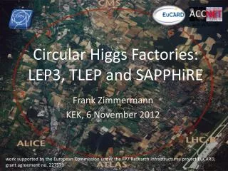
A circular e + e - collider to study H(125) properties - accelerator . Frank Zimmermann Frascati , 14 February 2013. many thanks to Roy Aleksan, Alain Blondel, John Ellis, Patrick Janot, Mike Koratzinos, Katsunobu Oide, Valery Telnov, Rogelio Tomas, Marco Zanetti .

E N D
A circular e+e- collider to study H(125) properties - accelerator Frank Zimmermann Frascati, 14 February 2013 many thanks to Roy Aleksan, Alain Blondel, John Ellis, Patrick Janot, Mike Koratzinos, Katsunobu Oide, Valery Telnov, Rogelio Tomas, Marco Zanetti work supported by the European Commission under the FP7 Research Infrastructures project EuCARD, grant agreement no. 227579
outline • motivation • machine proposals • parameters, lifetime, key concepts • various features • a long-term strategy • HF quality indicators • the path forward
circular HFs – a few examples SLAC/LBNL design: 27 km LEP3: 27 km TLEP (LEP4): 80 km near Geneva SuperTRISTAN in Tsukuba: 40 km Y. Cai, SLAC A. Blondel, J. Osborne, F. Zimmermann FNAL site filler, 16 km & FNAL VLLC 233 km ring K. Oide, KEK IHEP Chinese HF + Super pp Collider 50 or 70 km Q. Qin, IHEP T. Sen, E. Gianfelice-Wendt, Y. Alexahin, FNAL
LEP3, TLEP (LEP4)(e+e- -> ZH, e+e- →W+W-, e+e- →Z,[e+e-→t ) key parameters at the Z pole repeating LEP physics programme in a few minutes…
S. Henderson’s Livingston Chart: Luminosity TLEP-Z TLEP-W TLEP-H adding TLEP to the chart! TLEP-t Stuart Henderson, Higgs Factory Workshop, Nov. 14, 2012
circular HFs – beam lifetime • LEP2: • beam lifetime ~ 6 h • dominated by radiativeBhahba scattering with cross section s~0.215 barn • LEP3: • with L~1034 cm−2s−1 at each of several IPs: • tbeam,LEP3~18 minutes from rad. Bhabhascattering • → solution: top-up injection • additional beam lifetime limit due to beamstrahlung: • (1) large momentum acceptance (h≥ 3%), and/or • (2) flat(ter) beams and/or • (3) fast replenishing (H. Burkhardt) (A. Blondel) (V. Telnov, K. Yokoya, M. Zanetti)
circular HFs – beamstrahlung • simulation w 360M macroparticles • t varies exponentially wenergy acceptance h • post-collision E tail → lifetime t TLEP at 240 GeV: TLEP at 350 GeV: t>0.5 s at h=1.0% (4 IPs) t>5 s at h=1.5% t>50 s at h=2.0% t> 8 min at h=2.5% t>2 s at h=2.0% (4 IPs) t>12 s at h=2.5% t>50 s at h=3.0% t> 4 min at h=3.5% M. Zanetti (MIT)
circular HFs – beamstrahlung • simulation w 360M macroparticles • t varies exponentially wenergy acceptance h • post-collision E tail → lifetime t beam lifetime versus acceptance h for 1 IP:
beamstrahlung luminosity spectrum LEP3 & ILC: LEP3 beamstrahlung more benign than for linear collider M. Zanetti (MIT)
luminosity formulae & constraints SR radiation power limit beam-beam limit >30 min beamstrahlung lifetime (Telnov) → Nb,bx →minimize ke=ey/ex,by~bx(ey/ex) and respect by≥sz
LEP3/TLEP parameters -1 soon at SuperKEKB: bx*=0.03 m, bY*=0.03 cm SuperKEKB:ey/ex=0.25%
LEP2 was not beam-beam limited LEP3/TLEP parameters -2 LEP data for 94.5 - 101 GeV consistently suggest a beam-beam limit of ~0.115 (R.Assmann, K. C.)
circular HFs – arc lattice KEK design IHEP design Q. Qin K. Oide FNAL site filler SLAC/LBNL design T. Sen, E. Gianfelice-Wendt, Y. Alexahin Y. Cai
circular HFs – final-focus design KEK design IHEP design Q. Qin K. Oide βx*=20cm, βy*=0.5cm FNAL site filler SLAC/LBNL design T. Sen, E. Gianfelice-Wendt, Y. Alexahin Y. Cai
circular HFs - momentum acceptance with synchrotron motion & radiation (sawtooth) KEK design before optics correction KEK design after optics correction ±1.1% ±1.3% K. Oide ±2.0% ±1.6% FNAL site filler SLAC/LBNL design Y. Cai T. Sen, E. Gianfelice-Wendt, Y. Alexahin
circular HFs – top-up injection double ring with top-up injectionsupports short lifetime & high luminosity A. Blondel top-up experience: PEP-II, KEKB, light sources
top-up injection SPS as LEP injector accelerated e±from 3.5 to 20 GeV (later 22 GeV) on a very short cycle: acceleration time = 265 ms or about 62.26 GeV/s Ref. K. Cornelis, W. Herr, R. Schmidt, “Multicycling of the CERN SPS: Supercycle Generation & First Experience with this mode of Operation,” Proc. EPAC 1988 assuming injection from the SPS into the top-up accelerator at the same energy of 20 GeV and final energy of 120 GeV: acceleration time = 1.6 seconds total cycle time = 10 s looks conservative (→ refilling ~1% of the LEP3 beam, for tbeam~16 min) Ghislain Roy & Paul Collier
top-up injection: schematic cycle beam current in collider (15 min. beam lifetime) 100% 99% almost constant current energy of accelerator ring 120 GeV injection into collider injection into accelerator 20 GeV 10 s
top-up injection at PEP-II/BaBar Before Top-Up Injection After Top-Up Injection average ≈ peak luminosity (H≈1)! J. Seeman
top-up injection: feasibility HF 2012 conclusions (John Seeman, SLAC): Top-up injection will work for a Circular Higgs Factory. A full energy injector is needed. A synchrotron injector will work the best, but is more than is needed (60 Hz!). A rapidly ramped storage ring is likely adequate (4 sec). The detectors will need to mask out the buckets with damping injected bunches during data taking as had been done for PEP-II/BaBar: BaBar trigger masking: Mask all of ring a few tens of turns. Mask injected bunch area for 1250 turns or about 0.9 msec.
PEP-II Hübner factor J. Seeman, 7 Dec. 2012 for one day (July 3, 2006): H≈0.95 for one month (August 2007): H≈0.63
Circular Collider & SR Experience … CESR BEPC LEP Tevatron LEP2 HERA DAFNE PEP-II KEKB BEPC-II LHC SuperKEKB (soon) 3rd generation light sources 1992ESRF, France (EU) 6 GeV ALS, US 1.5-1.9 GeV 1993 TLS, Taiwan 1.5 GeV 1994ELETTRA, Italy 2.4 GeV PLS, Korea 2 GeV MAX II, Sweden 1.5 GeV 1996APS, US 7 GeV LNLS, Brazil 1.35 GeV 1997 Spring-8, Japan 8 GeV 1998BESSY II, Germany 1.9 GeV 2000ANKA, Germany 2.5 GeV SLS, Switzerland 2.4 GeV 2004SPEAR3, US 3 GeV CLS, Canada 2.9 GeV 2006: SOLEIL, France 2.8 GeV DIAMOND,UK 3 GeV ASP, Australia 3 GeV MAX III, Sweden 700 MeV Indus-II, India 2.5 GeV 2008SSRF, China3.4 GeV 2009PETRA-III, Germany 6 GeV 2011ALBA, Spain 3 GeV well understood technology & typically exceeding design performance within a few years
Emittances in Circular Colliders & Modern Light Sources Y. Funakoshi, KEK LEP3 Top up injection essential for achieving small vertical emittance Lenny Rivkin, 2nd LEP3 Day TLEP (240) R. Bartolini, DIAMOND
circular HFs: synchroton-radiation heat load LEP3 and TLEP have 3-10 times less SR heat load per meter than PEP-II or SPEAR! (though higher photon energy) N. Kurita, U. Wienands, SLAC
TLEP polarization 80% at the Z pole LHeC equilibrium polarisation vs ring energy, full 3-D spin tracking results (D. Barber, U. Wienands, in LHeC CDR, J. Phys. G: Nucl. Part. Phys. 39 075001) “… by adopting the levels of alignment that are now standard for synchrotron-radiation sources and by applying harmonic closed-orbit spin matching, there is reason to hope that high polarisation in a flat ring can … be obtained”
TLEP3 key components • tunnel • SRF system • cryoplants • magnets • injector ring • detectors • tunnel is main cost: • 3x LEP tunnel = 2.1 BCHF • 9x LHeC tunnel cost estimate = 2.25 BCHF • inofficial/official TLEP tunnel cost ~2.5 BCHF
TLEP3 key issues • SR handling and radiation shielding • optics effect energy sawtooth • [separate arcs?! (K. Oide)] • beam-beam interaction for large Qs • and significant hourglass effect (K. Ohmi) • IR design with even larger momentum • acceptance • integration in LHC tunnel (LEP3) • Pretzel scheme for TERA-Z operation? • impedance effects for high-current running • at Z pole
shielding & activation for Ec>1 MeV A. Fasso 3rd TLEP3 Day LEP design study extended up to 130 GeV
transverse impedance & TMCI • LEP bunch intensity was limited by TMCI: Nb,thr~5x10¹¹ at 22 GeV • LEP3 with 700 MHz: at 120 GeV we gain a factor 5.5 in the threshold, which almost cancels a factor (0.7/0.35)3 ~ 8 arising from the change • in wake-field strength due to the different RF frequency • LEP3 Qs~0.2, LEP Qs~0.15: further 25% increase in TMCI threshold? • only ½ of LEP transverse kick factor came from SC RF cavities , • LEP3 beta functions at RF cavities might be smaller than in LEP, • LEP3 bunch length (2-3 mm) is shorter than at LEP injection (5-9 mm) • M. Lamont, SL-Note-98-026 (OP) • instability threshold, feedback etc for Tera-Z operation w 1 A current? question by K. Yokoya, Feb. 2013
Circular & Linear HF: peak luminosity vs energy LEP3 , TLEP x 4 IPs LEP3/TLEPwouldbe THE choice for e+e- collision energies up to ~370 GeV K. Yokoya, KEK
vertical rms IP spot sizes in nm in regular font: achieved in italics: design values by*: 5 cm→ 1 mm LEP3/TLEP will learn from ATF2 & SuperKEKB
recent comment by eminent German particle physicist: “TLEP is much riskier and its performance highly uncertain; while the ILC performance numbers are very conservative” [?] extrapolation from past experience
a glance at LHC & LHC upgrades LHCis the 1st Higgs factory! ECoM=8-14 TeV,1034cm-2s-1 total cross section at 8 TeV: 22 pb 1 M Higgs produced so far – more to come 15 H bosons / min – and more to come HL-LHC (~2022-2030) will deliver ~9x more H bosons! ECoM=14 TeV,5x1034cm-2s-1 with luminosity leveling 8 14 TeV: ggHx1.5 F. Cerutti, P. Janot VHE-LHC: new 80 km tunnel ECoM=84-104 TeV,x1034cm-2s-1 HE-LHC: in LHC tunnel (2035-) ECoM=33 TeV,x1034cm-2s-1 20-T dipole magnet 80 km tunnel 16 T magnets over 80 km (Ex6) likely “easier” than 20 T magnets over 27 km (Ex2.5)!? 14 33 TeV: ggH HHx6 E. Todesco, L. Rossi,P.. McIntyre J. Osborne, C. Waaijer, S. Myers
possible long-term strategy TLEP (80 km, e+e-, up to ~350 GeV c.m.) PSB PS (0.6 km) SPS (6.9 km) LHC (26.7 km) LEP3 (e+e-, 240 GeV c.m.) VHE-LHC (pp, up to 100 TeVc.m.) same detectors! (E. Meschi) also: e± (120 GeV) – p (7 & 50 TeV) collisions ≥50 years of e+e-, pp, ep/A physics at highest energies
parameters for LHC HL-LHC, HE-LHC and VHE-LHC (examples) O. Dominguez & F. Zimmermann
arrangement in VHE-LHC tunnel VHE-LHC injector ring “LER” (using transmission line magnet) Lucio Rossi CLIC workshop 28 Jan. 2013 H. Piekarz, Proc. HE-LHC’10, p. 101 20-T magnet 30 mm V gap 50 mm H gap Bin = 0.5 T Bextr = 1.5 T
VHE-LHC’s LER magnets compatible with TLEP and VLHeC – 100 MW SR Lucio Rossi CLIC workshop 28 Jan. 2013 • advantages: • cheap, likeresistivemagnets • central gap couldbeshortcircuited • magnetsseparated: provideselectronsat 120 GeV and protons at 5 TeV/beam • limitedcryopower (HTS) in shadow of SCRF cavities • SC cablesdevelopedalready for SC links (HiLumi) and power applications • SR takenat 300 K
Lucio Rossi CLIC workshop 28 Jan. 2013 Lucio Rossi’s «plan for all» according to Physicsneeds, the 80 km tunnel can: • be alternative to HE-LHC • or becomplementary to HE-LHC • accomodateatnegligibleextra-cost TLEP and VLHeC • modular detector design allows evolution from TLEP-H/TLHeCto VHE-LHC 2017-2020 iscriticaltime!
Mikhail S. Gorbachev If what you have done yesterday still looks big to you, you haven’t done much today.
maximum TLEP luminosity Mike Koratzinos maximum theoretical luminosity is Max. of 0.1 total power limit (100 MW SR) Beam-beam limit For LEP3 this is =6cm-1 (0.6/0.1cm-1). For TLEP =0.75/0.1cm-1. Difficult to go beyond this without nanobeam /crab-waist scheme at 120 GeV
even higher TLEP luminosity? • charge compensation (CC) – counteracting the electric field of the incoming beam by a second beam of opposite charge • 4-beam collisions at DCI, Orsay, 1971 - not a spectacular success • new idea (V. Telnov, M. Koratzinos): use charge compensation to suppress beamstrahlung and push luminosity in crab-waist scheme
Mike Koratzinos artist’s impression of CC-TLEP main ring magnets Thermal power management Vacuum management Vacuum chamber Accelerator ring magnets Clockwise e- anticlockwise e+ Clockwise e+ anticlockwise e-
Valery Telnov’s estimate for CC TLEP V. Telnov, 3 TLEP3 Day
HF quality indicators • readiness / maturity • cost , electrical power • peak luminosity , #IPs • integrated luminosity • Hübner (H) factor = integrated lumi/(peak lumi x calendar time for physics) HLEP≈0.2, HLHC ≈0.2, HKEKB≈0.7, HPEP-II≈0.7 • commissioning time • expandability
HF Accelerator Quality (My Opinion) inspired by S. Henderson, FNAL
the path forward • set up international collaboration(s) & work structure • ERC proposal on large-acceptance IR design by Rogelio Tomas • TLEP Design Study Proposal for ECFA • INFN-LNF could play a key role! • goal: publish TLEP Conceptual Design Study Report by end of 2014!
ERC Consolidation Grant • Proposal “LEAF”– Draft • PI: Rogelio Tomas • includes international • network for feeding new • ideas, guidance, local • support for experimental • tests, review & collaboration
draft work topics: TLEP accelerator • parameter optimization with regard to lifetime and luminosity, at different energies, &different tunnels • RF system design, prototyping & integration for collider and accelerator ring • optics design for collider ring including low-beta IRs, off-momentum dynamic aperture, different energies • beamstrahlung: lifetime, steady state beam distribution, dependence on tune etc. • beam-beam interaction with large hourglass effect • emittancetuning studies, errors, tolerances, etc. • optics design and beam dynamics for the accelerator ring, ramping speed etc • impedance budget, CSR, instabilities • cryogenics system design • magnets design: collider ring dipole, accelerator ring dipole, low-beta quadrupole • radiation, shielding, cooling for 100 MW SR power • vacuum system design • engineering study of 80-km tunnel • design of injector complex including e+ source, and polarized e- source • machine detector interface, integration of accelerator ring at detector (s), low-beta quadrupoles, shielding (e.g. against beamstrahlung)? • injection scheme • polarization, Siberian snakes, spin matching, acceleration & storage, polarized sources (19 September 2012)