Download
1 / 22
220 likes | 375 Views
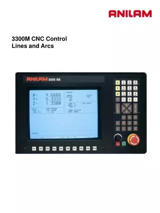
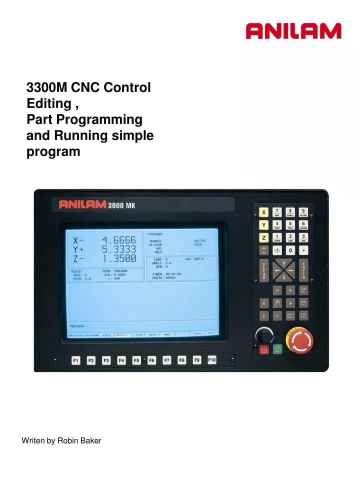
3300M CNC Control Editing , Part Programming and Running simple program. Writen by Robin Baker . Press to enter editor. Teach. Tool. Drill. Mill. Exit. Pocket. Calc. Misc. Edit. Sub. Draw. F10. F7.

E N D
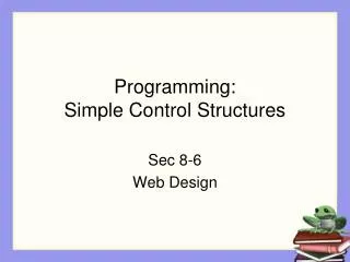
3300M CNC Control Editing , Part Programming and Running simple program Writen by Robin Baker
Press to enter editor. Teach Tool Drill Mill Exit Pocket Calc Misc Edit Sub Draw F10 F7 F2 F3 F6 F8 F2 F1 F5 F4 F9 Dimension can be entered into by F2 Rapid , F3 feed or Modal. Simulation draw allows checking program before run in auto. Drilling canned cycles. Pocketing canned cycles. Mill operations. Tool Page. Calculators Pocket , Right-angled triangle & Geometry. Various auxiliary functions. Miscellaneous functions Exit to program page 1.
Modal Teach Rapid Line Teach F4 F1 F2 F3 F1 Before entering Teach Mode you must create a program. Press to enter teach mode. Exit from Teach Mode. Inputs a Rapid move. Inputs a Line move. Inputs a Modal move. 1. Rapid input. 2.Line input 3.Modal input Modal meaning it will do this move the same as previous move , in this case Line. 2.
Drilling Cycles Basic :- Drills a hole one shot. Pecking :- Drills in steps depending on the amount of peck entered. Boring :- Feeds in And out of hole. Chip Break::- Used for deep holes , peck and then at specified depth retract all the way out of hole. Drill Tapping:- Taps hole feeds and speed must be calculated correctly. Drilling Off:- Drilling must be turn OFF when done. Pattern:- Program a regular pattern of holes giving Number of holes, Distance between holes. Bolt Hole:- Full or partial bolt hole may be programmed. F3 3.
Pocket F4 Face:- Allows use face of a surface. Rect. Profile:- Cleans up the inside or outside of a rectangle. Circ. Profile:- Cleans up the inside or outside of a circle. Rectangular:- Makes a rectangular pocket. Circular:- Makes a circular pocket. Frame:- Makes a rectangular pocket with an island. Hole:- Opens up an existing hole. Irregular:- Program a profile and clean out the pocket area. Mold Rotation:- Program two axis profile around a center line and cut three axis radial cavity. Elbow Milling:- Cuts a three axis radial cavity. 4.
Mill Rapid F5 F2 Mill Active one has a border These are various way of entering a line or rapid move. 5.
Arc F4 This is the default for arc’s and will always come up looking this way. There two other chooses , end point and center or center and angle. Note the center icon is high lighted. With this arc the machine is capable of milling a thread. It needs an X , Y and Z end point X , Y center point and Rev’s. With Z starting at zero the inputs shown on left would cut a 10 TPI thread. 6.
Enter a feedrate on line by itself. Put spindle speed on of it’s own. Change planes XY,XZ or YZ. Inch or MM. Enter fixture offset , this is an absolute shift relative to Machine Zero. Incremental Zero shift. Returns machine to home. Programs an ellipse with comp inside or outside. Spiral gives the ability to program tapered threads. Feed RPM Plane Unit Offset SetZero Home Ellipse Spiral More Prev F9 F4 Pressing this key will bring up following box menu. Press to return to previous screen. 7.
X,Y zero 5.” 1.” 1.” 3.” 1.5” 5.25” We will now write a program to center drill and drill this part, we will use a subroutine in this program because we are going to use the same dimensions twice. A subroutine is a mini program outside of the Main program that will be Called into the Main program. Program lines are in boldprint. 8.
1 Rapid 1 Rapid + ABS _ 5 Tool INC Save Save Save F10 F10 F10 E N T E R Press Press Set the control in absolute. Use to toggle between Abs/Inc. Dim Abs 1. When !/Rapid key is pressed a box as show on left will appear. Rapid Z0.000 Tool# 0 Rapid to Z home. 2. Press 3. Rapid X -4.000 Y 2.0 000 Rapid to tool change position. 5/Tool key is press screen will look as shown on left. The Mcode would only be necessary if a tool changer is installed. Tool# 1 Call tool #1 4. 9.
Drill Save F10 F3 E N T E R F3 Drill is selected this box will appear. These are your chose of how you are going to drill the hole , the first time we will use Basic for the center drill , the second time we will use pecking for the drill. E N T E R When is pressed the screen will appear as above. Zdepth = depth of hole. StartHgh = Distance above Surface you are drilling into. ReturnHgt = Distance above to retract to before moving to next hole. Feed = Feedrate Tool# = Tool# may be entered here. BasicDrill Zdepth -0.125 StartHgt 0.1000 Feed 10.0 5. 10.
MCode Sub EndSub Prev Dwell Loop EndMain Call RMS Sub F10 F4 F8 F5 F7 F2 F9 F1 F8 F3 F6 Press Sub Function key will change as below. Enter subroutine number.A subroutine is a program entered after main program and call into main program using a Call. Entered at the end of a subroutine. Bring a subroutine into main program. Ends main program. Repeats operation desired number of times. Allow subroutines to be Rotated , Mirrored or Scaled. Enters Dwell into program , this is also available on a hot key. Enters an Mcode into program , also available as a hot key. Return to previous screen. Not used. 11.
1 Rapid 1 Rapid Call Save Save F10 F10 F3 Press E N T E R Press Key number 1 6. Call 1 We have now finished the with the first tool. Press 7. Rapid Z0.000 Tool# 0Rapid to Z home. Press Rapid x -4.000 Y 2.0000Rapid tool change position. 8. 12.
Press 5 Tool Drill Save Save F10 F10 F3 Press 9. Tool# 2 Load tool #2 Press down arrow key to high light Pecking , press E N T E R Input values 10. PeckDrill Zdepth -1.0000 StarHgt 0.1000 Peck 0.2500 Feed 12.0 13.
1 Rapid 1 Rapid Save EndMain Save Call F10 F10 F4 F3 Press E N T E R Press Key number 1 11. Call 1 We have now finished the with the first tool. Press 12. Rapid Z0.000 Tool# 0Rapid to Z home. Press 13. Rapid x -4.000 Y 2.0000Rapid tool change position. Press 14. EndMain 14.
1 Rapid Prev Sub Drill F3 F9 F1 EndSub F2 Press Press Sub 1 Press Rapid X 1.0000 Y -1.0000 Rapid X 5.0000 Rapid X 5.2500 Y -3.0000 Rapid X 1.5000 Drilling must now be turn off as soon as last hole is drilled Press Press E N T E R High light Drilling Off press When only one axis is changing , only enter that axis. EndSub Program for this part is now complete. 15.
This is above program will look in control. 1. 2. 3. 4. 5. 6. 7. 8. 9. 10. 11. 12. 13. 14. 15. 16. 17. 18. 19. 20. 21. Dim Abs Rapid Z 0.0000 Tool# 0 (See note 2 below) Rapid X -4.0000 Y 2.0000 Tool# 1 BasicDrill ZDepth -0.1250 StartHgt 0.1000 Feed 10.0 Call 1 Rapid Z 0.0000 Tool# 0 ( See note 3 below ) Rapid X -4.0000 Y 2.0000 Tool# 2 PeckDrill ZDepth -1.0000 StartHgt 0.1000 Peck 0.2500 Feed 12.0 Call 1 Rapid Z 0.0000 Tool# 0 (See note 3 below) Rapid X -4.0000 Y 2.0000 EndMain Sub 1 Rapid X 1.0000 Y -1.0000 Rapid X 5.0000 Rapid X 5.2500 Y -3.0000 Rapid X 1.5000 Drilling Off EndSub Note If running parts on a machine with Homing a fixture offset may be added to program at Line #2 or #3 to get to part zero. With Bed Mill Z0 Tool#0 not required , just move Z axis up plus to a convenient height to change Tools.( I.e. Z5.0000.) 16.
Run View Draw Display Parms Exit Prev F10 F9 F6 F4 F3 F9 F5 F7 F2 F8 F1 Now that the part is programmed , we need to verify that it is correct. To do this we use Draw . Press to return to main edit screen. Press to enter Draw Mode. Draw F2 Not used Exit draw mode. Runs program in simulation draw. There are four views available XY,XZ,YZ and Iso. Calculates the window size to show complete part. Not used Not used Not used Draw parameters. Exit to main edit screen. 17.
Display F5 Press box will pop-up as shown below high light will be on fit. Use arrow keys to move high light up and down. Press E N T E R Red lines are Rapid moves. White Lines are Feed moves. Yellow are axis lines. Blue represent the tools sizes ,In this case tool #1 is center drill with .0000 Diameter and tool #2 is .5000 drill. 18.
Tool Cancel S.Step Run Text Motion F10 F3 F1 F2 F6 F9 F8 F5 F3 F4 F7 When is press soft key will change as below. Auto Will run program all the way through. Ever time Start is pressed runs one program line. Runs a move ever time Start is pressed. If high lighted will scroll text. Will show tools if high lighted. Rapid Displays Rapid moves when high lighted. Starts draw moves one line in S Step or Motion. Start Stop draw until Start is pressed. Hold Cancel current drawing. Not used 19.
Exit Tool Exit OFFSET F10 F10 F9 F5 F1 F6 CalibX CalibY Program has been written and checked on simulation graphics , it is now time to set Part zero and Tool offsets. Press twice to return to Manual page . Using Jog keys find edge of part or center of hole where you want X0 and Y0 are to be located . If machine does not have homing press X0 display will change to zero on X axis , use same procedure on Y axis . If machine has Home Jog to X0 , Y0 as above then press Softkeys will change as shown below. Press If machine is at X0 press Do the same with Y Press E N T E R 20.
Exit AUTO F10 F5 F6 Calib Z You are now back at the tool Page . The thing to do is set tool length Offsets. Check to see that Tool #0 is active . Put tool #1 into spindle jog down to top of part . Check to see that high light is on Tool #1 . Now press Move spindle up , put in tool #2 and repeat above process , until all tools offsets are set and press . Control is now back at Manual and ready to cut part. Press Put Tool #1 in spindle press Machine will stop on Tool Change press Machine will rapid X and Y position of first hole and then Z rapid to .1000 above part . Next it will then feed to give depth and rapid back out of the hole and rapid to next hole and repeat process until all holes are drilled. It will now on Tool Change and repeat process for tools #2 and #3. 21.