Download
1 / 18
180 likes | 268 Views
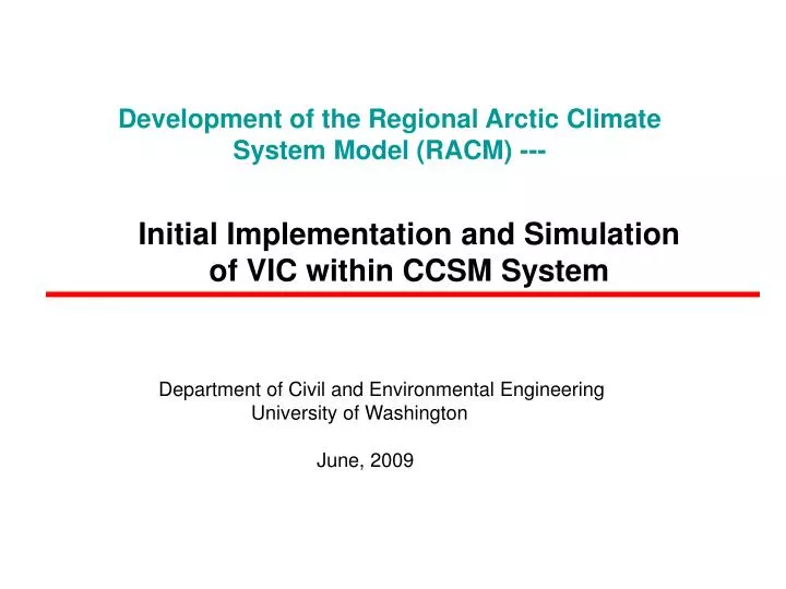
Development of the Regional Arctic Climate System Model (RACM) ---. Initial Implementation and Simulation of VIC within CCSM System. Department of Civil and Environmental Engineering University of Washington June, 2009. Modeling Framework.

E N D
Development of the Regional Arctic Climate System Model (RACM) --- Initial Implementation and Simulation of VIC within CCSM System Department of Civil and Environmental Engineering University of Washington June, 2009
Modeling Framework Global Domain 4x5 resolution runs: January 1999, July 1999 Configuration F (CAM/VIC) • Features specific to Cold-Land Processes: • Two-layer energy balance snow model (Storck et al. 1999) • Frozen soil/permafrost algorithm (Cherkauer et al. 1999, 2003) • Lakes and wetlands model (Bowling et al. 2004) • Blowing snow algorithm (Bowling et al. 2004)
January 1999 Latent Heat Comparison VIC NCEP/NCAR II CLM
July 1999 Latent Heat NCEP/NCAR II VIC CLM
January 1999 Sensible Heat Comparison NCEP/NCAR II VIC CLM
July 1999 Sensible Heat VIC NCEP/NCAR II CLM
January 1999 Snow Water Equivalent Height NCEP/NCAR II VIC CLM
July 1999 Snow Water Equivalent Height NCEP/NCAR II VIC CLM
January 1999 Surface Air Temperature VIC NCEP/NCAR II CLM
July 1999 Surface Air Temperature NCEP/NCAR II VIC CLM
Longwave Radiation Flux CAM/VIC CAM/CLM Jan July
Shortwave CAM/VIC CAM/CLM Jan July
VIC output variables to CPL clm_l2a%qflx_evap_tot = out_data->evap/ 3600 clm_l2a%fsa = out_data->net_short clm_l2a%eflx_lwrad_out = out_data->rad_temp * out_data->rad_temp * out_data->rad_temp * out_data->rad_temp * 5.67 / 100000000 clm_l2a%eflx_lh_tot = out_data->latent clm_l2a%eflx_sh_tot = out_data->sensible clm_l2a%q_ref2m = out_data->surf_humid clm_l2a%t_ref2m = out_data->surf_temp clm_l2a%t_rad = out_data->rad_temp clm_l2a%h2osno = out_data->snow_depth[0]/100
Albedo ??? Currently VIC output one albedo value to four albedos required by CAM. clm_l2a%albd(g,1) clm_l2a%albd(g,2) = out_data ->albedo clm_l2a%albd(g,2) clm_l2a%albd(g,2) • Does WRF needs four albedos from LAND?
Wind Stress ??? VIC calculates wind stress according the equation in CLM: clm_l2a%taux = forc_rho * forc_u / out_data->aero_resist ; clm_l2a%tauy = forc_rho * forc_v/ out_data->aero_resist ;
Wind Stress Aerodynamic Resistance CAM/VIC crashes at step 9 due to anomalously high surface stress (about -1000) over part of South America, which is related to anomalouslylow aerodynamic resistance (about 0.1).
Current solution in…… wrf_vic_interface.c if( out_data->aero_resist < 1 ){ resist = out_data->aero_resist * 100; out_data->aero_resist = resist; } if( out_data->aero_resist < 10 && out_data->aero_resist >1 ) { resist = out_data->aero_resist * 10; out_data->aero_resist = resist; } • WRF provide aerodynamic resistance to LAND?
Future Work Parrellizing VIC land model in CCSM system to improve computing performance. Upgrading VIC4.0.4 to VIC 4.1.0 Implement VIC routing model into RACM Rout surface and subsurface runoff into rivers