Download
1 / 52
530 likes | 965 Views
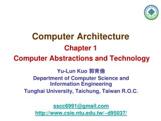
컴퓨터구조 Computer Architecture 디지털공학 ( 선수과목 ) Digital Engineering. Logic and Computer Design Fundamentals (Fourth Ed. 2008) M. Morris Mano & Charles R. Kime. Computer Architecture. 강의자료 , 공지 : 홈페이지 konkuk.ac.kr konkuk.ac.kr /~ ikpark , ikpark .konkuk.ac.kr, digcom .konkuk.ac.kr

E N D
컴퓨터구조Computer Architecture디지털공학 (선수과목)Digital Engineering Logic and Computer DesignFundamentals(Fourth Ed. 2008) M. Morris Mano & Charles R. Kime
Computer Architecture • 강의자료, 공지 : 홈페이지 konkuk.ac.kr • konkuk.ac.kr/~ikpark, ikpark.konkuk.ac.kr, digcom.konkuk.ac.kr • 교재 : Logic and Computer Design Fundamentals (4thed. 2008 Mano) • 영어 원서, 한글 저서(번역서 등) • digital circuit, digital circuit + digital computer • presentation 자료로 강의 :칠판 판서로 해달라? • 받아 적는다고설명을 못 들음. 빠뜨리는 것 없게 하기 위해 • PowerPoint 파일 .pptx : IE, chrome (google.co.kr) • 예습 →강의시간 →복습 →다음 강의시간에 잠깐 복습, 질문 • 상담 시간 : 강의 계획서, 재실(C동322호)일 때는 언제나 가능 Computer Architecture
Computer Architecture • 공학인증관련 학교 • 개 강 : 사전설문조사(~2주) • 중간고사 : 10월20일(월) 08:40~ 중간 " • 기말고사 : 12월15일(월) 08:40~ 최종 " 강의평가 • 대학 1년은 1년이 아니다. • 확실하고 구체적인 목표를 정하라. • 학점이 목적이 아니다 : 학점은 ? 실력도 아니다 →상대평가 Computer Architecture
Computer Architecture • 과제: 각 chapter 가 끝나면 문제 풀이 → copy 하지 마라 • 혼자 힘으로 풀 수 있는 것만 풀어서 제출하라 할 때 제출 • 설계 프로젝트 : • Verilog HDL(Hardware Description Language), • FPGA(Field Programmable Gate Array), • 실습보드(development and education board)를 이용 • 개별 설계 프로젝트 : 7장 10절 이후 학기 중 제출 • DashWatch, Handheld Game PIG 택1 :설계,시연,보고서 • 팀별 설계 프로젝트 : 3명이 팀, 학기 말 까지 • 제안 발표 : 3명 각자 본인 것을 발표, 발표자료 제출 • 중간 발표 : 팀별로 하나 선택하여 발표, 발표자료 제출 • 최종 발표 및 시연: 보고서 제출 Computer Architecture
Memory Control unit Datapath CPU Inputs : keyboard, mouse Outputs : LCD Input/Output synchronous or asynchronous Computer Architecture • computer architecture : used to encompass the whole of computer • instruction set architecture, organization, hardware • digital computer : typical digital system • digital engineering : analysis & designdigital system (circuits) • digital system : store, move, processinformation • manipulate two values • sequential circuits, • combinational circuits (Ch. 8,13) (Ch. 5,7) (Ch. 9) Ch. 9,10,11 (Ch. 12) Computer Architecture
More on the Generic Computer Computer Architecture
Logic and Computer Design Fundamentals Digital Engineering • Ch. 1 : Digital Systems and Information • Ch. 2 : Combinational Logic Circuits • Ch. 3 : Combinational Logic Design • Ch. 4 : Arithmetic Functions and HDLs • Ch. 5 : Sequential Circuits • Ch. 6 : Selected Design Topics • Ch. 7 : Registers and Register Transfers • Ch. 8 : Memory Basics • Ch. 9 : Computer Design Basic • Ch. 10 : Instruction Set Architecture • Ch. 11 : RISC and CISC Central Processing Units • Ch. 12 : Input-Output and Communication • Ch. 13 : Memory Systems Computer Architecture Logic and Computer Design Fundamentals
Digital Engineering • Ch. 1 : Digital Systems and Information • Ch. 2 : Combinational Logic Circuits • Ch. 3 : Combinational Logic Design • Ch. 4 : Arithmetic Functions and HDLs • Ch. 5 : Sequential Circuits Logic and Computer Design Fundamentals
Computer Architecture • Ch. 6 : Selected Design Topics • Ch. 7 : Registers and Register Transfers • Ch. 8 : Memory Basics • Ch. 9 : Computer Design Basic • Ch. 10 : Instruction Set Architecture • Ch. 11 : RISC and CISC Central Processing Units • Ch. 12 : Input-Output and Communication • Ch. 13 : Memory Systems Computer Architecture
Computer Architecture • Ch. 6 Selected Design Topics • 6-1 The Design Space • 6-2 Gate Propagation Delay • 6-3 Flip-Flop Timing • 6-4 Sequential Circuit Timing • 6-5 Asynchronous Interactions • 6-6 Synchronization and Metastability • 6-7Synchronous Circuit Pitfalls • 6-8 Programmable Implementation Technologies Logic and Computer Design Fundamentals
Computer Architecture • Ch. 7 : Registers and Register Transfers • 7-1 Registers and Load Enable • 7-2 Register Transfers • 7-3 Register Transfer Operations • 7-4 A Note for VHDL and Verilog Users Only • 7-5 Microoperations • 7-6 Microoperations on a Single Register • 7-7 Register Cell Design • 7-8 Multiplexer and Bus-Based Transfers for Multiple Reg.s • 7-9 Serial Transfer and Microoperations • 7-10 Control of Register Transfer • 7-11 HDL Representation for Shift Registers and Counters-VHDL • 7-12 HDL Representation for Shift Registers and Counters-verilog • 7-13 Microprogrammed Control Logic and Computer Design Fundamentals
Computer Architecture • Ch. 8 Memory Basics • 8-1 Memory Definitions • 8-2 Random-Access Memory(RAM) • 8-3 SRAM Integrated Circuits • 8-4 Array of SRAM ICs • 8-5 DRAM ICs • 8-6 DRAM Types • 8-7 Array of DRAM ICs Logic and Computer Design Fundamentals
Computer Architecture • Ch. 9 Computer Design Basics • 9-1 Introduction • 9-2 Datapaths • 9-3 The Arithmetic/Logic Unit • 9-4 The Shifter • 9-5 Datapath Representation • 9-6 The Control Word • 9-7 A Simple Computer Architecture • 9-8 Single-Cycle Hardwired Control • 9-9 Multiple-Cycle Hardwired Control Logic and Computer Design Fundamentals
Computer Architecture • Ch. 10 Instruction Set Architecture • 10-1 Computer Architecture Concepts • 10-2 Operand Addressing • 10-3 Addressing Modes • 10-4 Instruction set Architecture • 10-5 Data-Transfer Instructions • 10-6 Data-Manipulation Instructions • 10-7 Floating-Point Computation • 10-8 Program Control Instruction • 10-9 Program Interrupt Logic and Computer Design Fundamentals
Computer Architecture • Ch. 11 RISC and CISC Central Processing Unit • 11-1 Pipelined Datapath • 11-2 Pipelined Control • 11-3 The Reduced Instruction Set Computer • 11-4 The Complex Instruction Set Computer • 11-5 More on Design Logic and Computer Design Fundamentals
Computer Architecture • Ch. 12 Input-Output and Communication • 12-1 Computer I/O • 12-2 Sample peripherals • 12-3 I/O Interfaces • 12-4 Serial Communication • 12-5 Modes of Transfer • 12-6 Priority Interrupt • 12-7 Direct memory Access Logic and Computer Design Fundamentals
Computer Architecture • Ch. 13 Memory Systems • 13-1 Memory Hierarchy • 13-2 Locality of Reference • 13-3 Cache Memory • 13-4 Virtual Memory Logic and Computer Design Fundamentals
Digital Engineering (and Lab) • analysis & design : digital (logic) circuit (system) • digital system : • store, move, process information • manipulate two values • logic : false, true • electronic circuit : low, high voltage • easy, simple • number : 0, 1 → binary number • combinational, sequential circuit • typical digital system : digital computer Digital Engineering (and Lab)
Digital Engineering (and Lab) • human - decimal : digital system – binary • number system, conversion, encoding • number system : binary, hexadecimal • decimal no. : 0~9 decimal digit • binary no. : 0, 1 binary digit (bit) • hexadecimal no. : 0~9, A,B,C,D,E,F • conversion between number systems Digital Engineering (and Lab)
Digital Engineering (and Lab) • information representation : encoding • code • decimal codes : • BCD, Excess-3 • alphanumeric codes : • ASCII, unicode • Gray code Digital Engineering (and Lab)
Digital Engineering (and Lab) • mathematical notation : • todescribe operational properties of digital circuits • used to analyze and design circuits • Boolean algebra : used • to describe interconnection of digital gates • to designlogic ckt.sthroughmanipulation of Boolean expression • basic identities : commutative, associative, distributive law, • DeMorgan’stheorem • binary logic • AND, OR, NOT operation : AND, OR, NOT gate(inverter) Digital Engineering (and Lab)
+v +v output inputs outputs Digital Engineering (and Lab) digital circuit input : : • analysis & design : digital (logic) circuit (system) • analysis : digital circuit, inputs→ outputs • using truth table (state table), Boolean expression, simulation tool • design :inputs, outputs→ digital circuit ⇒ verification (analysis) • air conditioner, heater, … • input :toggle switch, • output : LED(Light Emitting Diode), push button switch, … 7-segment LED, … Digital Engineering (and Lab)
Combinational Circuit • combinational circuit : • consists of input variables, output variables, logic gates, and interconnections • can be specified by a truth table • also can be described by Boolean functions • n input variables : 2n possible binary input combination • m output : m Boolean functions Logic and Computer Design Fundamentals
Digital Engineering (and Lab) • design : • gates (AND, OR, NOT, NAND, NOR, … ) : Ch.2 • decoder, multiplexer : Ch.3 • PLD (Programmable Logic Device, PROM, PLA, PAL) : Ch.6, • custom IC : full custom IC, semi custom IC, • FPGA (Field Programmable Gate Array) : 실습 • gates : Digital Engineering (and Lab)
Design Procedure • design : start from specification of problem • culminate in a logic diagram or • netlist that describe a logic diagram • 1. specification : • 2. formulation : Truth Table • 3. optimization : • apply two-level and multiple-level optimization • 4. technology mapping : • 5. verification : Logic and Computer Design Fundamentals
Digital Engineering (and Lab) • 2-level optimization (simplification) • product term, sum term, minterm, maxterm • canonical form : sum of minterms, product of maxterms • standard form : sum of products, product of sums • cost criteria : gate input cost • map method • map manipulation • implicant, prime implicant, essential prime implicant • don’t-care condition • multiple-level optimization • other gates • buffer, 3-state buffer, NAND, NOR, EX-OR, EX-NOR Digital Engineering (and Lab)
Design Procedure • EX. 3-1 Design of a BCD-to-Excess-3 Code Converter • EX. 3-2 Design of a BCD-to-Seven-Segment Decoder • reduced by finding common termsfrom two or more map • some common terms : may not be prime implicantsof individual fn. • EX. 3-3 Design of a 4-bit Equality Comparator • divide-and-conquer approach Logic and Computer Design Fundamentals
Digital Engineering (and Lab) • decoder : CLC that performed decoding • conversion of n-bit input code to m-bit output code with n≤m≤2n • multiplexer : data selector • CLC thatselects binary information from one of many input lines • anddirects information to a single output line Digital Engineering (and Lab)
MUX EX. combinational circuit using decoder • 1 bit binary adder : • S(X,Y,Z) = ∑m(1,2,4,7) • C(X,Y,Z) = ∑m(3,5,6,7) 0 Z Z Z’ Z Z’ 1 Z Logic and Computer Design Fundamentals
EX. combinational circuit using multiplexer • F(A,B,C,D) = ∑m(1,3,4,11,12,13,14,15) Logic and Computer Design Fundamentals
Digital Engineering (and Lab) • PLD (Programmable Logic Device, PROM, PLA, PAL) : Digital Engineering (and Lab)
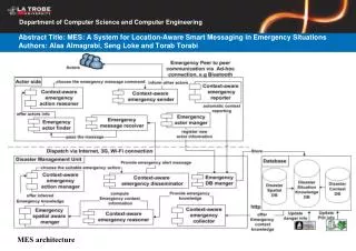
Digital Engineering (and Lab) • FPGA (Field Programmable Gate Array) : 실습 • HDL (Hardware Description Language) : VHDL, verilog HDL • Altera DE2 development and education board : FPGA 실습보드Fig. • Altera Cyclone II 2C35FPGA device : • Altera design software : Quartus II web edition (v 9.0) • design circuit, pin assignment, simulation FPGA 실습보드 FPGA +v outputs inputs digital circuit +v : : pin Digital Engineering (and Lab)
Complements • complements for base-r system : two type • 1. r’s(radix) complement : 2’s, 10’s • 2. (r-1)’s(diminished radix) complement : 1’s, 9’s • binary no. N(n digit) • 1’s : (2n– 1) – N • 2’s : 2n– N for N ≠ 0, 0 for N = 0 • 2n : consists of a 1 followed by n 0’s • (2n– 1) : represent by n 1’s • 1’s complement : • obtained by subtracting each digit from 1(r – 1) • therefore, formed by changing all 1’s to 0’s, 0’s to 1’s • (r-1)’s complement : • obtained by subtracting each digit from r-1 Logic and Computer Design Fundamentals
Complements • 2’s complement : • (1) obtained by adding 1 to 1’s complement • Ex. 2’s of 101100 : 010011 + 1 = 010100 • (2) formed by leaving all least significant 0’s and the first 1 unchanged and then 1’s with 0’s and 0’s with 1’s all other higher significant bits • r’s complement : • 1st nonzero digit is subtracted from the base r, and remaining digits to the left are replaced with (r-1) minus their value • complement of complement : 2n– (2n– N) = N Logic and Computer Design Fundamentals
Signed Binary Numbers • computers : because of hardware limitation • represent everything with 1’s & 0’s, including the sign of a number • sign : most significant position of an n-bit no. • 0 : positive, 1 : negative • binary number : integer • ex. +9, -9 represented in binary with 8-bits • +9 -9 • 1. signed-magnitude representation : 00001001 10001001 • 2. signed-1’s complement representation : 00001001 11110110 • 3. signed-2’s complement representation : 00001001 11110111 Logic and Computer Design Fundamentals
Unsigned/Signed Binary Addition/Subtraction • (M) - (N) = (M) +(-(N) ) • 1. M + (2n– N) = M – N + 2n = 2n– (N – M) • 2. if M ≥ N : sum will produce an end carry, 2n, which is discarded ; what is left is result M – N • 3. if M < N : sum does not produce an end carry and is equal to 2n– (N – M), which is 2’s complement of N – M. • the correction is performed to take 2’s complement of sum and to place a minus sign in front • (±A) - (±B) = (±A) +(-(±B) ) • 1. take 2’s complement of subtrahend(including sign bit) • 2. add it to minuend(including sign bit) • 3. end carry is discarded Logic and Computer Design Fundamentals
Unsigned/Signed Binary Addition/Subtraction • overflow detection • unsigned addition subtraction • C = 1 overflow no correction step • C = 0 no overflow correction step : -(2’s) • signed addition subtraction • V = 0 no overflow no overflow • V = 1 overflow overflow : (C : actual sign bit) • V = Cn Cn-1 Logic and Computer Design Fundamentals
Sequential Circuit • Fig. : Block Diagram of a Sequential Circuit • interconnected combinational circuit, storage element • storage element : stored binary information Logic and Computer Design Fundamentals
Sequential Circuit • sequential circuits : two model • 1. Mealy model circuits : ex. Fig. 5-15 • outputs dependon inputs, as well as on states • 2. Moore model circuits : ex. Fig. 5-16 • outputs dependonlyonstates Logic and Computer Design Fundamentals
Digital Engineering (and Lab) • Fig. 5-13 Standard Graphics Symbols for Latches & FF Digital Engineering (and Lab)
Digital Engineering (and Lab) Digital Engineering (and Lab)
Design Procedure • procedure for the design of sequential circuits : • 1. specification : • 2. formulation : state diagram or state table • 3. state assignment : if state diagram, obtainstate table • assignbinary codes to the states in the table • 4. Flip-Flop input equations determination : • select FF type or types : D-FF, JK-FF, T-FF • drive the FF input equations • 5. output equations determination : • 6. optimization : • 7. technology mapping : • 8. verification : Logic and Computer Design Fundamentals
Design Procedure • EX. 5-3 Design of a Sequence Recognizer • assign binary code : • binary Gray code • One-Hot code : one FF per one state • EX. 5-4 Design of a BCD-to-Excess-3 Decoder • reduce state : find equivalent state • state machine diagram ← state diagram • use of Boolean expressions and equations Logic and Computer Design Fundamentals
EX.5-3 : Design a Sequence 1101 Recognizer • 1. specification : • to recognize occurrence of sequence of bits 1101on X • by“making Z equal to 1 when previous three inputs were 110 and current input is a 1. otherwise, Z equals 0” • Mealy model : preceding specification “…” • 2. formulation : obtainstate diagram • 3. state assignment : obtain state table • assign binary codes to the states in the table Logic and Computer Design Fundamentals
(Gray code) AB • 3. state assignment : obtainstate table • assign binary codes to the states in the table • 4. Flip-Flop input equations determination : • select FF type or types : D-FF • A(t+1) = DA(A,B,X) = m(3,6,7) = AB + BX • B(t+1) = DB(A,B,X) = m(1,3,5,7) = X • 5. output equations determination : • Z(A,B,X) = m(5) = AB’X Logic and Computer Design Fundamentals
EX.5-3 : Design a Sequence 1101 Recognizer • 6. optimization : • Logic Diagram for the Gray-Coded Sequence Recognizer with D FF • A(t+1) = DA(A,B,X) = AB + BX, B(t+1) = DB(A,B,X) = X, Z(A,B,X) = AB’X Reset Logic and Computer Design Fundamentals
(one FF per one state) • 3. state assignment : obtainstate table • assign binary codes to the states in the table • 4. Flip-Flop input 5. output equations determination : • A(t+1) = DA = AX’ + BX’ + DX’ = (A + B + D)X’ • B(t+1) = DB = AX + DX = (A + D)X • C(t+1) = DC = BX + CX = (B + C)X • D(t+1) = DD = CX’ • Z = DX Logic and Computer Design Fundamentals
Fig. 5-24 Logic Diagram for the One-Hot Coded SequenceRecognizer with D Flip-Flops • A(t+1) = DA = (A+B+D)X’ • B(t+1) = DB = (A + D)X • 회로 수정할 것 • C(t+1) = DC = (B + C)X • D(t+1) = DD = CX’ • Z = DX • initial reset state A : 1000 s Reset Clock Reset Ch.5 Sequential Circuits
Computer Arcitecture • Altera DE2 development and education board : FPGA 실습보드Fig. • Altera Cyclone II 2C35FPGA device : Fig. • 33,216 LEs • 105 M4K RAM Blocks(4Kbits + 512 parity bits) • 483,840 total RAM bits • 35 embedded multipliers(two 9x9-bit or one 18x18-bit multiplier) • 4 PLLs(phase-locked loop) • 475 user I/O pins (672-pin package) • Altera design software : Quartus II (9.0) Web edition • VHDL(Very-High-Speed IC HDL), Verilog HDL(Hardware Description Language), schematic diagram, state diagram • simulation Logic and Computer Design Fundamentals
Altera DE2 development and education board • FPGA 실습보드 Digital Engineering and Lab