Download
1 / 6
60 likes | 140 Views
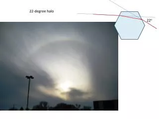
Ultra-sensitive HALO monitor. N. Vinogradov, A. Dychkant, P. Piot. Motivation (courtesy to Daniel Mihalcea). Keep bunch charge at 1nC and decrease the radius at cathode from 3mm to 2mm => Halo formation downstream of SRF cavities (rings in the transverse plane separated from the beam core).

E N D
Ultra-sensitive HALO monitor N. Vinogradov, A. Dychkant, P. Piot
Motivation (courtesy to Daniel Mihalcea) Keep bunch charge at 1nC and decrease the radius at cathode from 3mm to 2mm => Halo formation downstream of SRF cavities (rings in the transverse plane separated from the beam core). No Halo Beam requirements (original design): • Charge/pulse: 133pC (Iavg = 100 mA) • Transverse emittance < 3m • Longitudinal emittance < 100 ps-keV • Energy 7 MeV • Energy spread < 1% 16% of particles 19% of particles
Scanning actuator Plate with narrow slit Schematic layout of the HALO monitor “Cleaning” dipole Primary beam Beamlet “Cleaned” signal from HALO Photo Multiplier Tube in magnetic shielding Signal from PMT Scintillator with array of fibers Long flexible shielded lightguide High voltage to PMT
Can we clean the beamlet good enough? Momentum distribution (p/mc) in collimated beam right after it passed the slit Computer model: SHOWER is used to simulate the scattered particles passed the collimator along with the true beamlet ELEGANT is used to track the signal from the collimator to the detector location through the cleaning dipole Spatial distribution of beam particles right after they passed the slit Slit at 1 mm from beam axis Spatial distribution (m) of beam particles right after they passed the slit (green) and at the location of detector head (red) Momentum distribution (p/mc) of collimated beam at the location of detector head Initial 10 MeV electron beam: Gaussian distribution for coordinates and momentums X, Y RMS = 2 mm Tungsten plate of 2 mm thickness Slit is 1 mm wide Slit at 7 mm from beam axis Useful signal
Who is who? 1. “Good” scenario: the true HALO signal is easy to distinguish Integrated signal from PMT (what we actually see) I True HALO signal (signal picked up by scintillator) r 2. “Worse” scenario: still can measure HALO Background signal picked up by scintillator: should be small or repeatable I repeatable Background signal picked up by PMT: can be suppressed by shielding the PMT r 3. “Worst” scenario: background is large and not repeatable ←beam is not stable ← there is no stable HALO anyway
Background test at AWA (Argonne) 6 MeV electron beam; 15 psec pulse; 50 nC bunch charge Beam on scintillator was not measured but calibration on lab source shows signal at the level of 5·10-9 for 10 single electrons! Lightguide PMT Hamamatsu R580 Shielded scintillating head in fixture 3·10-9 Fiber Kuraray Y-11 outer diameter 1.2mm 5·10-12 Scintillating material BC-408 with grooves for the fibers (no glue)