Download
1 / 25
250 likes | 363 Views
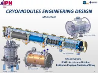
Type IV Cryomodule (T4CM) Design Team Formation & Technical Discussions. H. Carter CERN – 1/16-17/2006. Outline. General Purpose of this meeting Meeting goals: Organizational Technical Future meetings---format, when, where, frequency, etc. General items.

E N D
Type IV Cryomodule (T4CM) Design Team Formation & Technical Discussions H. Carter CERN – 1/16-17/2006
Outline • General • Purpose of this meeting • Meeting goals: • Organizational • Technical • Future meetings---format, when, where, frequency, etc.
General items • First of all a thank you to our CERN colleagues for hosting this meeting on very short notice • Jean-Pierre Delahaye • Vittorio Parma • Second, thank you all for taking time from your busy schedules to attend this important meeting • Meeting Agenda: • Monday, January 16 • Introduction and meeting overview H. Carter • Organizational issues H. Carter • Institutional Participation Inst. Representatives • Lunch • Technical Discussions T. Peterson, D. Mitchell • Tuesday, January 17 • Technical Discussions T. Peterson • Lunch • Continuation of Technical Discussions T. Peterson • Summary Review • Next meeting • Adjourn
General: Meeting Attendees I am sending around a list of known participants, but it is not all inclusive. If your name, institution and email address is not on the list, please add it to the list so that you can receive the meeting summary writeup via email.
Purpose of this meeting • What this meeting is: • a continuation of our previous cryomodule working group meetings • Oct. 2004 SLAC meeting • Oct. 2005 SMTF Collaboration meeting at FNAL • What this meeting is not: • a workshop---there will be few (if any) formal presentations
How we got to this point • 1st Cryomodule meeting at SLAC (Oct. 2004) • working group formed to begin identifying the “next generation” cryomodule design issues • 2nd Cryomodule meeting at the SMTF Collabor-ation meeting at Fermilab (Oct. 2005) • continued working group discussion of features to be incorporated in T4CM • created rough estimate of the time required to complete the T4CM design • Other relevant meetings----Snowmass 2005 and the recent Frascati meeting
Goals for this meeting • Formation of an international T4CM design team • This does not mean a “design by committee” • Definition of what a T4CM is • What items are incorporated from the possibilities • Identification of a comprehensive list of tasks to be accomplished • Creation of work packages to address tasks • Assignment of work packages to T4CM design team members • Establish a timeline for T4CM design completion
Organizational Issues • Design team formation • Regional structure and leadership • Sort of a “mini-GDE” structure • Need to identify regional leader(s) • Design tools, standards, and data exchange • Should design tools be common or regional in nature? • What design standard(s) should be used? • Example: Type III+ cryomodule vs. FNAL design requirements • What format should be used for data exchange? • Integration issues • to be coordinated by regional leadership • information exchange
T4CM Europe T4CM Design Team International Design Team Formation T4CM Americas T4CM Asia KEK FNAL CERN DESY JLab Others? Milan INFN SLAC Pisa
Institutional Participation in T4CM • At this point in my talk I would like to have brief presentations from representatives from each Institution interested in participating in the T4CM design effort, then I will continue: the order will be alphabetical, except I will discuss Fermilab’s plan last: • CERN V. Parma • DESY R. Lange • INFN Milan C. Pagani • INFN Pisa F. Bedeschi • JLAB J. Prebyl • KEK N. Ohuchi • SLAC J. Weisend • FNAL H. Carter • Speakers have been asked • to present: • institutional resources • resource availability • tasks which they are interested • in working on
ILC Americas T4CM Design Team • Task Manager: T. Peterson • Task Engineering: D. Mitchell: Mechanical design T. Nicol: Cryostat & supports M. McGee: Vibration measurement & analysis S. Tariq: FEA analysis of mechanical components (tuners,cavities, etc.) J. Tompkins: SC quadrupole & correctors V. Kashikin: SC quadrupole & correctors J. Weisend: Cryostat & cryogenics K. Jobe: Cryostat & cryogenics • Task Designer(s): Contract Designers • Task Scientific Input: H. Edwards / S. Mishra/ K. Ranjan/ N. Solyak/ Paul Lebrun / H. Padamsee Deliverable: Complete T4CM drawing package ready for procurement by end of CY07
Arriving at a T4CM Design 1st Qtr 2nd Qtr 3rd Qtr 4th Qtr 1st Qtr 2nd Qtr 3rd Qtr 4th Qtr 1st Qtr 2006 2007 2008 Define design features Perform engineering analyses Complete drawing packages Procure components All Components in house and ready for assembly
Who will build the T4CM? • FNAL plans: • The third cryomodule to be assembled at Fermilab will be a T4CM design, probably without a quadrupole/BPM package, though a predetermined space will be left for this package and an instrumented mockup (correct size and weight) will be installed.
Schedule for CM Assembly at FNAL 1st Qtr 2nd Qtr 3rd Qtr 4th Qtr 1st Qtr 2nd Qtr 3rd Qtr 4th Qtr 1st Qtr 2006 2007 2008 1st T3CM from DESY kit 3.9GHz CM for DESY TTF 2nd T3CM from FNAL components
Who will build the T4CM? • DESY plans: • The next cryomodule to be assembled at DESY will be a Type III+ design, designated Cryomodule #6, and will contain 8 cavities with accelerating gradients of > 35MV/m. • After Cryomodule 6, the kit for the first FNAL cryomodule will be assembled, then a spare Type II cryomodule, designated Cryomodule #7, for TTF will be assembled.
Who will build the T4CM? • KEK plans: • KEK is currently working on a cryomodule design that they plan to assemble at KEK in 2006. This cryomodule will contain 4 cavities of the low loss design with accelerating gradients of > 35MV/m. • Two such cryomodules are planned to be built and tested.
BCD has taken an unnecessarily risky path (in my opinion) • Somehow the T4CM rather than the Type III+ cryo-module has become the design adopted in the BCD: • this is bad---no T4CM has been built and tested---it may not work • proponents argue that the T4CM is close enough to the T3CM design that it doesn’t matter, so this is okay. Is it? • this is bad---no T4CM cost information will be available as a basis for the cost estimate of the RDR • proponents argue that the T4CM is close enough to the T3CM design that it doesn’t matter, so this is okay. Is it? • the cost of the XFEL CM (which closely resembles the T3CM in design and performance specification) will be the only good basis for costing the ILC cryomodule for the RDR • Main linac quadrupole spacing • 32 cavities per quadrupole (24 recommended by WG1)
BCD: Cryomodule configuration Baseline 10MW klystron drives 24 TESLA cavities. considering 7% WG loss and 11% overhead for 35MV/m operation Cavities divided into three cryomodules, Quad package in every 4-th cryomodules, Cos(2)type Quad + corrector windings+BPM, supported from GRP at center post, <10µm bunch-to-bunch resolution BPM Cavity spacing 283mm Contradiction with GG2-BCD! this slide taken from H. Hayano’s talk “BCD Input from WG2”
ACD: Cryomodule configuration Alternatives • 12 cavities in one cryomodule, • Cavity spacing 250mm~180mm, • HOM readout, • Quad-BPM in separate cryostat, • Putting movers on center support post • and cryomodule support, • Reduce Quad aperture to ~35mm, • 1µm resolution BPM this slide taken from H. Hayano’s talk “BCD Input from WG2”
BCD • Much detail still missing and needs to be supplied • tables of parameters • tables of tolerance • figures (cartoons) of basic layouts • lattices • … this slide taken from one of Nick Walker’s talks
General Interactions • Critical items for other work to proceed • cavity length • cavity-to-cavity spacing • Quadrupole/corrector/BPM package design • overall cryomodule length: • required in order to define main linac layout for lattice considerations • required to define civil construction and cryogenic system requirements
Interactions: ILC Linac Layout • Per request from Chris Adolphsen: • One of the goals of the GDE meeting at KEK on Jan 19-20 is to better define the ILC linac layout. To this end, we have been asked to provide working assumptions as to: • 1) the length of cryomodules with and without quads 2) the external support of cryomodules (e.g. from the floor or ceiling) 3) beamline and insulating vacuum segmentation 4) cryogenic maintenance length and the additional space required between segments 5) the space required to convert from cold to warm sections 6) the refrigerator spacing, capacities and space requirements We hope to answer some of these items at this meeting but not all can be answered at this time
Interactions in support of RDR effort • RTML: P. Tenebaum has requested coordination of our efforts with the Ring-To-Main-Linac efforts. He states that the • RTML includes 4 cryomodules in its first-stage bunch compressor (BC1) and 57 cryomodules in its second-stage compressor (BC2), for a total of 61 modules per side (e- side and e+ side) • RTML cryomodules do not need to be operated at 31.5 MV/m, but will be standard main linac cryomodules that are always run at lower gradients • Possibility of one or two crab cavity cryomodules per side for beam diagnostics and other longitudinal diagnostics
Interactions in support of RDR effort • BDS: A. Seryi has requested information in support of the crab cavity for the Beam Delivery System • The crab-cavity is the only SCRF cryomodule in the BDS • Basic parameters of the crab-cavity are given in BCD. We believe that the crab-cavity will be based on Fermilab CKM 3.9GHz deflecting cavity, however, design may be reoptimized. • Work needed to be done includes: • Defining specifications for the crab-cavity • Developing the design for the RDR • Producing the cost estimates. Crab cavities are not a topic of discussion for this meeting however I include this request in case someone here is interested on working on this problem.
Conclusions: • We are just beginning on T4CM but we have a solid base to work from---the Type III+ cryomodule---due to the many years of hard work by DESY and INFN Milan • The T4CM is an R&D effort and should not be confused with a proven design ready for use in specifying the main linac for the ILC. Pressure should not be placed on the design team for rapid turnaround of the design. • We have 17 tasks listed for discussion in the next day and a half, and we want to give each one at least a cursory look, so we may have to table some of the more controversial discussions and return to them if time permits • Future meetings---format, when, where, frequency, etc. Please consider this and give me suggestions at the meeting summary tomorrow afternoon • Thanks again to our CERN colleagues for hosting this meeting