Download
1 / 44
440 likes | 600 Views
Lecture 4. January 30, 2006. In this lecture. Z, I, S a /g and R values for tanks. Base shear coefficient. Seismic force V = (A h ) x (W) A h is base shear coefficient. Structural characteristics Depends on time period and damping. Design philosophy. Zone

E N D
Lecture 4 January 30, 2006
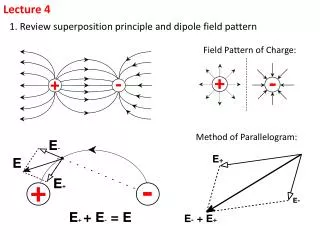
In this lecture • Z, I, Sa/g and R values for tanks E-Course on Seismic Design of Tanks/ January 2006
Base shear coefficient • Seismic force V = (Ah) x (W) • Ah is base shear coefficient Structural characteristics Depends on time period and damping Design philosophy Zone Depends on severity of ground motion E-Course on Seismic Design of Tanks/ January 2006
Base shear coefficient • Tanks have two modes • Impulsive • Convective • Seismic force • In impulsive mode, Vi = (Ah)i x impulsive weight • In convective mode, Vc = (Ah)c x convective weight • (Ah)i and (Ah)c are base shear coefficient in impulsive and convective modes, respectively E-Course on Seismic Design of Tanks/ January 2006
Base shear coefficient • Impulsive base shear coefficient • (Ah)i = (Z/2) x (I/R) x (Sa/g)i • Convective base shear coefficient • (Ah)c = (Z/2) x (I/R) x (Sa/g)c • Note, R has been used in (Ah)i as well as (Ah)c • Zone factor, Z • As per Table 2 of IS 1893(Part1):2002 • I, R, (Sa/g)i and (Sa/g)c will be discussed here • First, (Sa/g)i and (Sa/g)c E-Course on Seismic Design of Tanks/ January 2006
(Sa/g)i and (Sa/g)c • (Sa/g)i is average response acceleration for impulsive mode • Depends on time period and damping of impulsive mode • (Sa/g)c is average response acceleration for convective mode • Depends on time period and damping of convective mode E-Course on Seismic Design of Tanks/ January 2006
(Sa/g)i and (Sa/g)c • Sa/g is obtained from design spectra • Figure 2 of IS 1893(Part 1):2002 • These spectra are slightly modified for tanks • See next slide E-Course on Seismic Design of Tanks/ January 2006
(Sa/g)i and (Sa/g)c • Modifications are: • The rising portion in short period range from (0 to 0.1 sec) has been made constant • Very stiff structures have time period less than 0.1 sec • There may be modeling errors; actual time period may be slightly higher • As the structure gets slightly damaged, its natural period elongates • Ductility does not help in reducing response of very stiff structures • Hence, rising portion in the range 0 to 0.1 sec is usually disallowed by the codes. • Spectra is extended beyond 4 sec • Since convective time period may be greater than 4 sec. • Beyond 4 sec, 1/T variation is retained E-Course on Seismic Design of Tanks/ January 2006
(Sa/g)i and (Sa/g)c Sa/g Sa/g Sa/g Modified spectra Spectra of IS 1893 (Part 1):2002 For 5% damping E-Course on Seismic Design of Tanks/ January 2006
(Sa/g)i and (Sa/g)c Expressions for design spectra at 5% damping E-Course on Seismic Design of Tanks/ January 2006
(Sa/g)i and (Sa/g)c • Sa/g values also depend on damping • Multiplying factors for different damping are given in Table 3 of IS 1893(Part 1) • Recall from Lecture 2, higher damping reduces base shear coefficient or design seismic forces • Multiplying factor =1.4, for 2% damping • Multiplying factor = 1.0 for 5% damping • Multiplying factor = 0.8 for 10% damping • This multiplier is not used for PGA E-Course on Seismic Design of Tanks/ January 2006
Damping • Damping for impulsive mode • 5% of critical for RC tanks • 2% of critical for steel tanks • These are kept in line with IS 1893(Part 1) • Clause 7.8.2.1 of IS 1893(Part 1) suggests 5% damping for RC and 2% damping for steel buildings • However, IBC 2003 suggests 5% damping for all tanks • It suggests 5% damping for all types of buildings also E-Course on Seismic Design of Tanks/ January 2006
Damping • Damping depends on material and level of vibration • Higher damping for stronger shaking • Means that during the same earthquake, damping will increase as the level of shaking increases • We are performing a simple linear analysis, while the real behavior is non-linear • Hence, one fixed value of damping is used in our analysis E-Course on Seismic Design of Tanks/ January 2006
Damping • IS 1893(Part 1), needs to have a re-look at the damping values • Accordingly, damping values for tanks can also be modified E-Course on Seismic Design of Tanks/ January 2006
Damping • Damping for convective mode • 0.5% of critical for all types of tanks • Convective mode damping does not depend on material of tank or type of liquid stored • In Table 3 of IS 1893(Part 1):2002 • Multiplying factor for 0.5% damping is not given • Values are given for 0% and 2% damping • Linear interpolation shall not be done • Multiplying factor = 1.75, for 0.5% damping • In Eurocode 8 this multiplying factor is 1.673 • In ACI 350.3, this factor is 1.5 E-Course on Seismic Design of Tanks/ January 2006
Importance factor, I • Importance factor, I for tanks is given in Table 1 of the Guideline • This Table is reproduced here NOTE: Values of importance factor, I given in IS 1893 (Part 4) may be used where appropriate E-Course on Seismic Design of Tanks/ January 2006
Importance factor, I • I = 1.5, is consistent with IS 1893(Part 1) • IS 1893(Part 1):2002 suggests, I = 1.5 for • Hospital buildings • Schools • Fire station buildings, etc. • Tanks are kept at same importance level E-Course on Seismic Design of Tanks/ January 2006
Importance factor, I • Footnote below this Table is given to avoid conflict with I values of IS1893(Part 4) • IS 1893(Part 4) will deal with industrial structures • Not yet published • Some industries assign very high importance factor to tanks storing hazardous materials • Depending on their own requirements • For such tanks, Importance factor (I) will be as per part 4 E-Course on Seismic Design of Tanks/ January 2006
Response reduction factor, R • R values for tanks are given in Table 2 of the Guideline • This is reproduced in next two slides E-Course on Seismic Design of Tanks/ January 2006
Response reduction factor, R # These R values are meant for liquid retaining tanks on frame type staging which are inverted pendulum type structures. These R values shall not be misunderstood for those given in other parts of IS 1893 for building and industrial frames. * These tanks are not allowed in Zone IV and V E-Course on Seismic Design of Tanks/ January 2006
Response reduction factor, R + For partially buried tanks, values of R can be interpolated between ground supported and underground tanks based on depth of embedment. E-Course on Seismic Design of Tanks/ January 2006
Response reduction factor, R • R values for tanks are smaller than buildings • This is in line with other international codes • As discussed earlier, R depends on • Ductility • Redundancy • Overstrength • Tanks possess low ductility, redundancy and overstrength E-Course on Seismic Design of Tanks/ January 2006
Response reduction factor, R • First let us consider, elevated tanks on frame type staging • Staging frames are different than building frames • Hence, following footnote to Table 2 • These R values are meant for liquid retaining tanks on frame type staging which are inverted pendulum type structures. These R values shall not be misunderstood for those given in other parts of IS 1893 for building and industrial frames. • Staging frames are non-building frames and are different than building frames E-Course on Seismic Design of Tanks/ January 2006
Response reduction factor, R • There are critical differences between building frames and non-building frames • International codes clearly differentiate between these two types of frames • Building frames have rigid diaphragms at floor levels • Frames of staging do not have rigid diaphragms • In buildings, seismic weight is distributed along the height at each floor level • In elevated tanks, almost entire seismic weight is concentrated at the top • These are inverted pendulum type structures E-Course on Seismic Design of Tanks/ January 2006
Response reduction factor, R • Moreover in buildings, non-structural elements, such as infill walls, contribute significantly to overstrength • Staging are bare frames • In view of this, for staging with SMRF, R = 2.5 as against R = 5.0 for buildings with SMRF • With R = 2.5, base shear coefficient for elevated tanks on frame staging matches well with other international codes • See next slide E-Course on Seismic Design of Tanks/ January 2006
Response reduction factor, R • Comparison for frame staging • Zone and soil parameters are same used in Lecture 2 IBC 2003; Frame staging, R = 3.0 Guideline; Frame staging, R = 2.5 IS 1893:1984; All types of staging, K = 1.0 E-Course on Seismic Design of Tanks/ January 2006
Response reduction factor, R • Let us now consider, elevated tanks on RC shaft • They possess less redundancy and have single load path • RC shafts are usually thin shell and possess low ductility • There are analytical and experimental studies on ductility of hollow circularsections used in RC shafts • Some references are given on next slide E-Course on Seismic Design of Tanks/ January 2006
Response reduction factor, R • Studies on ductility of shaft • Zanh F A, Park R, and Priestley, M J N, 1990, “Flexural strength and ductility of circular hollow reinforced concrete columns without reinforcement on inside face”, ACI Journal 87 (2), 156-166. • Rai D C, 2002, “Retrofitting of shaft type staging for elevated tanks”, Earthquake Spectra, EERI, Vol. 18 No. 4, 745-760. • Rai D C and Yennamsetti S, 2002, “Inelastic seismic demand on circular shaft type staging for elevated tanks”, 7th National Conf. on Earthquake Engrg, Boston, USA, Paper No. 91. • Rao M L N, 2000, “Effect of confinement on ductility of RC hollow circular columns”, a Master’s thesis submitted to Dept. of Earthquake Engineering, Univ. of Roorkee, India. E-Course on Seismic Design of Tanks/ January 2006
Response reduction factor, R • These studies have revealed that ductility of shaft depends on • Thickness of wall (ratio of outer to inner diameter) • Axial force on shaft • Longitudinal and transverse reinforcement • Some results from these studies on ductility of RC shafts are discussed in next few slides E-Course on Seismic Design of Tanks/ January 2006
Effect of Axial Load on Ductility Figure from Rai (2002) Ast/Ag = ratio longitudinal reinforcement to concrete area. P = axial load on shaft fc’ = characteristic strength of concrete Ag = gross area of concrete Hollow circular section E-Course on Seismic Design of Tanks/ January 2006
Response reduction factor, R • In this figure, curvature ductility is plotted as a function of longitudinal reinforcement • These results are for inner (Di) to outer (Do) diameter ratio of 0.94. • If ratio of axial load (P) to ultimate load (fck.Ag) is 0.1 then, curvature ductility is about 9 for Ast/Ag = 0.02 • This value reduces to 3 for P/ (f’c.Ag) of 0.25 • Now, let us see some results on effect of shaft thickness E-Course on Seismic Design of Tanks/ January 2006
Effect of Shell Thickness on Ductility • Effect of ratio of inner to outer diameter (Di/Do) is shown • This result corresponds to P/(f’c.Ag) = 0.05 • Very low axial force ratio E-Course on Seismic Design of Tanks/ January 2006
Response reduction factor, R • For thin shaft with Di/Do = 0.95, curvature ductility is 12 • For longitudinal steel ratio Ast/Ag = 0.02 • This value increases to about 25 for thick shaft with Di/Do = 0.8 • Thus, thickness has significant effect on ductility • A thick shaft has reasonably good ductility E-Course on Seismic Design of Tanks/ January 2006
Response reduction factor, R • These analytical studies clearly indicate that thin RC hollow sections possess very low ductility • Issues connected with poor ductility of shaft, inadequate provisions of IS 1893:1984, and their correlation to behavior during recent earthquakes is discussed in following paper: • Rai D C, 2002, “Review of code design forces for shaft supported elevated water tanks”, Proc.of 13th Symposium on Earthquake Engineering , Roorkee, Ed. D K Paul et al., pp 1407 -1418. (http://www.nicee.org/ecourse/12_symp_tanks.pdf) E-Course on Seismic Design of Tanks/ January 2006
Response reduction factor, R • Based on all these considerations, R = 1.8 for shaft supported tanks • With this value of R, base shear coefficient for shaft supported tanks matches well with international codes • Comparison with IBC 2003 on next slide E-Course on Seismic Design of Tanks/ January 2006
Response reduction factor, R • Comparison for shaft staging • Zone and soil parameters are same as used in Lecture 2 IBC 2003; Shaft staging, R = 2.0 Guideline; Shaft staging, R = 1.8 IS 1893:1984; All types of staging, K = 1.0 E-Course on Seismic Design of Tanks/ January 2006
Response reduction factor, R • Some useful information on RC shaft is given in ACI 371-98 • ACI 371-98 , 1998, “ Guide for the analysis, design , and construction of concrete-pedestal water Towers”, American Concrete Institute, Farmington Hill, MI, USA. • It exclusively deals with tanks on RC shaft • It suggests same design forces as IBC 2003 • It gives information on: • minimum steel • construction tolerances • safety against buckling • shear design etc. E-Course on Seismic Design of Tanks/ January 2006
Response reduction factor, R • We have seen comparison with IBC 2003 • Comparison with other international codes is available in following documents: • Jaiswal, O. R. Rai, D. C. and Jain, S.K., 2004a, “Codal provisions on design seismic forces for liquid storage tanks: a review”, Report No. IITK-GSDMA-EQ-01-V1.0, Indian Institute of Technology Kanpur, Kanpur. (www.iitk.ac.in/nicee/IITK-GSDMA/EQ01.pdf ) • Jaiswal, O. R., Rai, D. C. and Jain, S.K., 2004b, “Codal provisions on seismic analysis of liquid storage tanks: a review” Report No. IITK-GSDMA-EQ-04-V1.0, Indian Institute of Technology Kanpur, Kanpur. (www.iitk.ac.in/nicee/IITK-GSDMA/EQ04.pdf ) E-Course on Seismic Design of Tanks/ January 2006
Response reduction factor, R • In the above two documents, following international codes are reviewed and compared: • IBC 2000 (now, IBC 2003) • ACI 350.3 • ACI 371 • AWWA D-110 and AWWA D-115 • AWWA D-100 and AWWA D-103 • API 650 and API 620 • Eurocode 8 • NZSEE recommendations (From New Zealand) • Priestley et al. (1986) E-Course on Seismic Design of Tanks/ January 2006
Response reduction factor, R • Now we know Z, I, R and Sa/g for tanks • One can now obtain base shear coefficient for impulsive and convective modes • An example follows. E-Course on Seismic Design of Tanks/ January 2006
Example • Example: An elevated water tank has RC frame staging detailed for ductility as per IS: 13920 and is located in seismic zone IV. Site of the tank has soft soil. Impulsive and convective time periods are 1.2 sec and 4.0 sec, respectively. Obtain base shear coefficient for impulsive and convective mode. Solution: Zone: IV Z = 0.24 From Table 2 of IS 1893 (PART I):2002, I = 1.5 From Table 1 of the Guideline R = 2.5 for RC frame with good ductility (SMRF) From Table 2 of the Guideline E-Course on Seismic Design of Tanks/ January 2006
Example on (Ah)i and (Ah)c Impulsive time period, Ti = 1.2 sec, and soil is soft, Damping = 5% (RC Frame) (Sa/g)i = 1.67/Ti = 1.67/1.2 = 1.392 (Clause 4.5.3 of the Guideline) Convective mode time period, Tc = 4.0 sec and soil is soft Damping = 0.5% (Clause 4.4 of the Guideline) Factor 1.75 is to be used for scaling up (Sa/g) for 0.5% damping (Clause 4.5.4 of the Guideline) (Sa/g)c = (1.67/Tc)x 1.75 = 1.67/4.0 x 1.75 = 0.731 E-Course on Seismic Design of Tanks/ January 2006
Example on (Ah)i and (Ah)c Base shear coefficient for impulsive mode (Ah)i= (Z/2) x (I/R) x (Sa/g)i = 0.24/2 x 1.5/2.5 x 1.392 = 0.10 Base shear coefficient for convective mode (Ah)c = (Z/2) x (I/R) x (Sa/g)c = 0.24/2 x 1.5/2.5 x 0.731 = 0.053 E-Course on Seismic Design of Tanks/ January 2006
At the end of Lecture 4 • R values for tanks are less than those for buildings.The basis for this is • Analytical studies • Provisions of international codes, and • Observed behavior of tanks • For tanks, slight modifications are recommended for design spectrum of IS 1893(Part1) • Damping for convective mode may be taken as 0.5% for all types of tanks E-Course on Seismic Design of Tanks/ January 2006