Download
1 / 30
300 likes | 447 Views
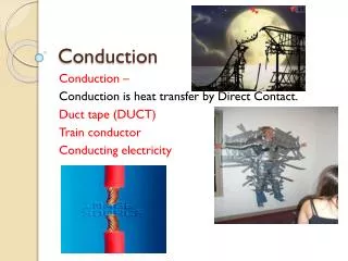
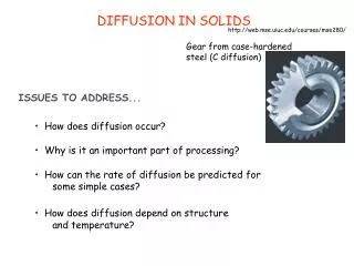
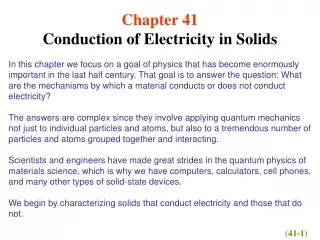
Chapter42 Conduction of Electricity in Solids. Classify solids electrically according to three basic properties:. 1. resistivity. 2. Temperature coefficient of resistivity. 3. Number density of charge carriers n. Use measurements of , and n to divide into three categories:.

E N D
Classify solids electrically according to three basic properties: 1. resistivity 2. Temperature coefficient of resistivity 3. Number density of charge carriers n Use measurements of , and n to divide into three categories: metals semiconductors insulators 42-2 The Electrical Properties of Solids silicon and diamond
42-3 Energy Levels in a Crystalline Solid According to Pauli exclusion principle
As (a) shows,in an insulator the highest band containing any electrons is fully occupied,and the Pauli exclusion principle keeps electrons from moving to occupied levels.The electrons in the filled band have no place to go,they are in gridlock,no one can move. 42-4 Insulators Sample Problem 42-1
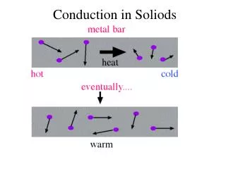
42-5 Metals As Fig.42-4b shows,the highest occupied energy level falls somewhere near the middle of an energy band.There are plenty of vacant levels at nearby higher energies into which electrons can jump. Electrons in its highest occupied band can easily move into higher energy levels within that band.
The total number of conduction electrons: The number density n of conduction electrons in a sample: The number of atoms in a sample: How Many Conduction Electrons Are There?
How Many Quantum States Are There? The density of states N(E) The quantity Kt,may be give to a conduction electron by the random thermal motions of the lattice.Only some few conduction electrons whose energies are close to the Fermi energy are likely to jump to higher energy levels due to thermal agitation. Conductivity at T>0
(a) (b) or Sample Problem 42-3
T=0 For ,the exponential term in Eq.42-6 is ,or zero.so P(E)=1 For ,the exponential term in Eq.42-6 is ,so P(E)=0 Fig.42-6b is a plot of P(E) for T=1000K. Note that if E=EF(no matter what the temperature T), the exponential term in Eq.42-6 is and P(E)=0.5 The Occupancy Probability P(E)
(a) (b) The Fermi energy of a given material is the energy of a quantum state that has the probability 0.5 of being occupied by an electron. Sample Problem 42-4
How Many Occupied States Are There? Sample Problem 42-5
In Fig.42-7a at all energies between E=0 and E=EF: In Fig.42-7a Because P(E)=1 ,we substitute Eq.42-5 into Eq.42-8, we find that Calculating the Fermi Energy
Number Density of Charge Carriers n Both the elections in the conduction band and the holes in the valence band serve as charge carriers.The electrons in the valence band,being negatively charged.In effect,the holes behave like moving particles of charge +e. The semiconductor has a much smaller energy gap Egbetween the valence band and conduction band.There is a real possibility that thermal agitation at room temperature will cause electrons to jump the gap from the valence band to the conduction band. 42-6 Semiconductors
Resistivity The resistivity of a material is . From the metal,this vast difference can be accounted for by the vast difference in n. Temperature Coefficient of Resistivity The resistivity of metal increases with temperature, is positive for metal. The resistivity of semiconductor decreases with temperature, is negative for semiconductor.
n-Type Semiconductors Semiconductors doped with donor atoms are called n-type semiconductors;the n stands for negative,to imply that the negative charge carriers introduced into the conduction band greatly outnumber the positive charge carries,which are the holes in the valence band.In n-type semiconductors,the electrons are called the majority carriers,and the holes the minority carriers. p-Type Semiconductors Semiconductors doped with acceptor atoms are called p-type semiconductors;the p stands for positive to imply that the holes introduced into the valence band,which behave like positive charge carriers,greatly outnumber the electrons in the conduction band.In p-type semiconductors,holes are the majority carriers and electrons are the minority carriers.
42-8 The p-n Junction A p-n junction (Fig.42-11a) is a single semiconductor crystal that has been selectively doped so that one region is n-type material and the adjacent region is p-type material.Such junctions are at the heart of essentially all semiconductor devices.The transition from one region to the other is perfectly sharp,occurring at a single junction plane.
Electrons on the n side of Fig.42-11a that are close to the junction plane tend to diffuse across it and into the p side,where there are very few free electrons. Similarly,holes on the p side that are close to the junction plane tend to diffuse across that plane and into the n side,where there are very few holes.The motions of both the electrons and the holes contribute to a diffusion currentIdiff. Motions of the Majority Carriers Electrons diffusing through the junction plane from right to left in Fig.42-11a result in a buildup of space charge on each side of the junction plane,as indicated in Fig.42-11b. Holes diffusing through the junction
plane from left to right have exactly the same effect. The motions of both majority carriers —electrons and holes — contribute to the buildup of these two space charge regions,one positive and one negative. These two regions form a depletion zone. The buildup of space charge generates an associated contact potential differenceV0across the depletion zone,as Fig.42-11c shows.This potential difference limits further diffusion of electrons and holes across the junction plane.
These few holes and electrons are the minority carriers in the corresponding materials. Motions of the Minority Carriers Both types of carriers are swept across the junction plane by the contact potential difference and,together, constitute a drift current Idrift across the junction plane from right to left, as Fig.42-11d indicates. An isolated p-n junction is in an equilibrium state in which a contact potential differenceV0exists between its ends.At equilibrium,the average diffusion currentIdiffthat moves through the junction plane from the p side to the n side is just balanced by an average drift currentIdriftthat moves in the opposite direction.These two currents cancel because the net current through the junction plane must be zero;otherwise charge would be transferred without limit from one end of the junction to the other.
42-9 The Junction Rectifier Look now at Fig.42-12.It shows that,if we place a potential difference across a p-n junction in one direction(here labeled + and “Forward bias”),there will be a current through the junction.However,if we reverse the direction of the potential difference,there will be approximately zero current through the junction.
A p-n junction connected as a junction rectifier.The action of the circuit in (b) is to pass the positive half of the input wave form (a) but to suppress the negative half.The average potential of the input wave form is zero;that of the output wave form (c) has a positive valueVavg.
(a) The forward-bias connection of a p-n junction, showing the narrowed depletion zone and the large forward currentIF . (b) the back-bias connection, showing the widened depletion zone and the small back currentIB.
Fig.42-15 The energy can be emitted as a photon of energy hf at wavelength Fig.42-16 42-10 The Light-Emitting Diode (LED) Sample Problem 42-7
REVIEW & SUMMARY Metals The total number of conduction electrons: The number of atoms in a sample:
The number density n of conduction electrons in a sample: The density of states N(E) The occupancy probability P(E)
The density of occupied statesN0(E) Semiconductors n-type semiconductor p-type semiconductor The p-n Junction Applications of the p-n Junction The energy can be emitted as a photon of energy hf at wavelength