Download

1 / 50
500 likes | 600 Views
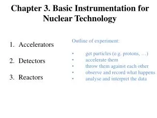
Chapter 3. Basic Instrumentation for Nuclear Technology. Accelerators Detectors Reactors. Outline of experiment:

E N D
Chapter 3. Basic Instrumentation for Nuclear Technology • Accelerators • Detectors • Reactors • Outline of experiment: • get particles (e.g. protons, …) • accelerate them • throw them against each other • observe and record what happens • analyse and interpret the data
1.Accelerators • History-Why • Particle Sources • Acceleration stage • Space charge • Diagnostics • Application
2. Detectors ionization chambersproportional countersGeiger-Muller counters Gas-Filled Radiation Detectors Scintillation Detectors Semiconductor Detectors Personal Dosimeters Others Particle identification Measurement theory Detection Equipment Photomultiplier tube • photographic films photographic emulsion plates • Cloud and Bubble Chambers E-ΔE, TOF
Ionization Chambers the voltage must be sufficiently high for effective collection of electrons. The average energy required to ionize a gas atom 30 eV/ion. If particles entering an air-filled detector deposit an average of 1 GeVS-1in the gas, the average current flowing through the chamber Current (A) is proportional to charges collected on electrode in ionization chambers. The current registered in the ionization chamber is proportional to the number of ion pairs generated by radioactivity
How can the sensitivities of ionization chambers be improved?What happens when the voltage is increased? Proportional Counters Gas Multiplication –+ –+–+–+ –+–+–+–+–+–+–+–+–+ –+–+–+–+–+–+–+–+–+–+–+–+–+–+–+–+–+–+–+–+–+–+–+–+–+–+–+–+–+–+–+–+–+–+–+–+ X00 V Proportional counters Gas multiplication due to secondary ion pairs when the ionization chambers operate at higher voltage. not only collect but also accelerate electrons
It should be noted, however, that the small mass and high energy of electrons make them drift 100,000 times faster than ions. Thus, the current is mainly due to the drifting electrons with only a small fraction due to the drift of ions. Despite the multiplication due to secondary ion pairs, the ampere-meters register currents proportional to the numbers of primary electrons caused by radiation entering the detectors. Thus, currents of proportional chambers correspond to amounts of ionization radiation entering the proportional chamber.
Geiger-Muller Counters 1X00 V Geiger counters count pulses. After each pulse, the voltage has to return to a certain level before the next pulse can be counted. Every ionizing particle causes a discharge in the detector of G-M counters.
high sensitivity No characterization of radioactivity. When the source has a very strong radioactivity, the pulses generated in the detectors are very close together. As a result, the Geiger counter may register a zero rate. In other words, a high radioactive source may overwhelm the Geiger counter, causing it to fail. keep this in mind. The zero reading from a Geiger counter provides you with a (false) sense of safety when you actually walk into an area where the radioactivity is dangerously high.
Scintillation Counters not based on ionization, but based on light emission. sodium iodide (NaI) crystal, contains 0.5 mole percent of thallium iodide (TlI) - activator, . Photons cause the emission of a short flash in the Na(Tl)I crystal.The flashes cause the photo-cathode to emit electrons. 10
Scintillation Detector and Photomultiplier tube Ionizing Radiation 11
The output pulses from a scintillation counter are proportional to the energy of the radiation. Electronic devices have been built not only to detect the pulses, but also to measure the pulse heights. The measurements enable us to plot the intensity (number of pulses) versus energy (pulse height), yielding a spectrum of the source.
-rayspectrum of 207mPb Gamma ray spectrum of 207mPb (half-life 0.806 sec) 207mPb Decay Scheme 13/2+____________1633.4 keV - Intensity (log scale) 1063 -1e4 569 5/2-____________569.7 keV 1063 -1e3 569 1/2-____________0.0 stable -1e2 -10 569 + 1063 -1 Energy Ionizing Radiation 13
Fluorescence Screens Fluorescence materials absorb invisible energy and the energy excites the electron. De-exciting of these electrons results in the emission of visible light. J.J. Thomson used fluorescence screens to see electron tracks in cathode ray tubes. Electrons strike fluorescence screens on computer monitors and TV sets give dots of visible light. Röntgen saw the shadow of his skeleton on fluorescence screens. Rutherford observed alpha particle on scintillation material zinc sulfide. Fluorescence screens are used to photograph X-ray images using films sensitive visible light. 14
Pulse height distribution of the gamma rays emitted by the radioactive decay of 24Na as measured by a Nal(Tl) scintillation detector.
2. Detectors ionization chambersproportional countersGeiger-Muller counters Gas-Filled Radiation Detectors Scintillation Detectors Semiconductor Detectors Personal Dosimeters Others Particle identification Measurement theory Detection Equipment Photomultiplier tube • photographic films photographic emulsion plates • Cloud and Bubble Chambers E-ΔE, TOF
Solid-state Detectors based on ionization, but different from ionization chambers A P-N junction of semiconductors placed under reverse bias has no current flows. Ionizing radiation enters the depleted zone excites electrons causing a temporary conduction. The electronic counter register a pulse corresponding to the energy entering the solid-state detector. + + depleted - - P + - N + + zone - - Negative Positive electronic counter See: bo.iasf.cnr.it/ldavinci/programme/Presentazioni/Harrison_cryo.pdf Ionizing Radiation
A simple view of solid-state detectors Energy required to free an electron from the valance band into the conduction band is called the band gap, which depends on the material: diamond, 5 eV; silicon, 1.1 eV; germanium, 0.72 eV. At room temperature, the thermal energy gives rise to 1010 carriers per cc. At liquid nitrogen temperature, the number of carriers is dramatically reduced to almost zero. At low temperature, it is easier to distinguish signals due to electrons freed by radiation from those due to thermal carriers. Solid-state detectors are usually made from germanium or cadmium-zinc-telluride (CdZnTe, or CZT) semiconducting material. An incoming gamma ray causes photoelectric ionization of the material, so an electric current will be formed if a voltage is applied to the material.
a CZT detector, an average of one electron/hole pair is produced for every 5 eV of energy lost by the photoelectron or Compton electron. This is greater than in Ge or Si, so the resolution of these detectors is not as good as HPGe or Si(Li) detectors.
Average Ionization Energy (IE eV) per Pair of Some Common Substances Material Air Xe He NH3 Ge‑crystalAverage IE 35 22 43 39 2.9
Personal Dosimeters Photographic Emulsions and Films Sensitized silver bromide grains of emulsion develope into blackened grains. Plates and films are 2-D detectors. Roentegen used photographic plates to record X-ray image. Photographic plates helped Beckerel to discover radioactivity. Films are routinely used to record X-ray images in medicine but lately digital images are replacing films. Stacks of films record 3-dimensional tracks of particles. Photographic plates and films are routinely used to record images made by electrons.
Cloud and Bubble Chambers The ion pairs on the tracks of ionizing radiation form seeds of gas bubbles and droplets. Formations of droplets and bubbles provide visual appearance of their tracks, 3-D detectors. C.T.R. Wilson shared the Nobel prize with Compton for his perfection of cloud chambers. Ionizing Radiation
At age 15, the Scottish physicist C.T.R. Wilson (1869-1959) spent a few weeks in the observatory on the summit of the highest Scottish hill Ben Nevis. He was intrigued by the color of the cloud droplets. He also learned that droplets would form around dust particles. Between 1896 and 1912, he found dust-free moist air formed droplets at some over-saturation points - ions
Image Recorded in Bubble Chambers Charge exchange of antiproton produced neutron-antineutron pair. p + p n + n (no tracks) Annihilation of neutron-antineutron pair produced 5 pions. n +n 3p+ + 2p- + ? Only these tracks are sketched. Ionizing Radiation
Bubble Chambers The Brookhaven 7-foot bubble chamberand the 80-inch bubble chamber Ionizing Radiation
Image from bubble chamber This image shows a historical event: one of the eight beam particles (K- at 4.2 GeV/c) which are seen entering the chamber, interacts with a proton, giving rise to the reactions K– p – K+ K0 K0 + – – 0 K– K+ + 0 0 p – Ionizing Radiation
2. Detectors ionization chambersproportional countersGeiger-Muller counters Gas-Filled Radiation Detectors Scintillation Detectors Semiconductor Detectors Personal Dosimeters Others Particle identification Measurement theory Detection Equipment Photomultiplier tube • photographic films photographic emulsion plates • Cloud and Bubble Chambers E-ΔE, TOF
5.9m 1.4m TOF 2 TOF 1 magnet 0.2m cooling Gas cell Test detector Solid target Stop detector 2 Start detector 1 Start detector 2 Collimators UNILAC beam Stop detector 1 Energy degrader Intensity attenuator Fig.1 Experimental set-up for the double time-of-flight (DTOF) system
Gas-Filled Radiation Detectors Scintillation Detectors Semiconductor Detectors Personal Dosimeters Particle identification Measurement theory Detection Equipment ionization chambersproportional countersGeiger-Muller counters Photomultiplier tube • photographic films photographic emulsion plates E-ΔE, TOF
Types of Measurement Uncertainties inherent stochastic uncertainty Systematic errors Sampling errors introduced by some constant bias or error in the measuring system and are often very difficult to assess since they arise from biases unknown to the experimenter. arise from making measurements on a different population from the one desired. Control of target parameters ensuring target homogeneity and stability is crucial and quite often more difficult to achieve than a high-quality beam.
Accuracy and precision Precision refers to the degree of measurement quantification as determined, for example, by the number of significant figures. Accuracy is a measure of how closely the measured value is to the true (and usually unknown) value. A very precise measurement may also be very inaccurate.
Uncertainty Assignment Based Upon Counting Statistics estimated using the binomial distribution Gaussian distribution. x ± s standard deviation of x. for replicate measurements the error is reduced by the square root of N.
Dead Time All radiation detection systems operating in the pulse mode have a limit on the maximum rate at which data can be recorded. significant dead time losses (m) Г is the dead time of the detector. mГ is the fraction of the time that the detector is unable to respond to additional ionization in the active volume of the detector When designing an experiment, it is advisable to keep these losses to a minimum. If possible, this means that mΓ < 0.05. For example, for a GM counter with a typical dead time of Γ = 100 μs, maximum count rate would be 500 counts/s.
Energy resolution the resolution of a semiconductor (Ge) detector is far superior to that of a NaI(T1) scintillation detector. energy spectra)recorded with a scintillation detector (upper graph) and a Ge detector (lower graph) of 662-keV y rays from a I37Cs source.
”Total reflection” Grazing-exit PIXE TPIXE p X-rays
SPE-File Sample P (g/kg) S (mg/kg) Ca (g/kg) Fe (mg/kg) Zn (mg/kg) Sr (mg/kg) 4043 CFD2 84 20 199 758 1229 69 4044 CFD2 83 22 209 748 1088 79 Non-destructive (damage) • cooling • Low beam current < 10 pA / 1μm 0.5 nA/ 1 mm 3 MeV Protons 100pA/μm 10 min No damage observed T. Sakai et al. / Nucl. Instr. and Meth. B 231 (2005) 112
2. Detectors ionization chambersproportional countersGeiger-Muller counters Gas-Filled Radiation Detectors Scintillation Detectors Semiconductor Detectors Personal Dosimeters Others Particle identification Measurement theory Detection Equipment Photomultiplier tube • photographic films photographic emulsion plates • Cloud and Bubble Chambers E-ΔE, TOF