Download
1 / 19
190 likes | 418 Views
UP AND DOWN CONTROLLED SPEED OF DC MOTOR IN EMBEDDED SYSTEM. SUBMITTED BY EDGEFX TEAM. ABSTRACT. The speed of motor is directly proportional to the DC voltage applied across its terminals. PWM (Pulse Width Modulation) wave can be used to control the speed of the motor

E N D
UP AND DOWN CONTROLLED SPEED OF DC MOTOR IN EMBEDDED SYSTEM SUBMITTED BY EDGEFX TEAM
ABSTRACT • The speed of motor is directly proportional to the DC voltage applied across its terminals. • PWM (Pulse Width Modulation) wave can be used to control the speed of the motor • the average voltage given or the average current flowing through the motor will change depending on the ON and OFF time of the pulses • The duty cycle of the wave controls its speed . On changing the duty cycle (ON time), we can change the speed
HARD WARE EQUIPMENTS • POWER SUPPLY • MICROCONTROLLER (AT89S52/AT89C51) • MOTOR DRIVER • DC MOTOR • PWM • PUSH BUTTONS • LCD • 1N4007 • LED • RESISTORS & CAPACITORS
EMBEDDED SYSTEMS Definition for :- EMBEDDED SYSTEMS • A combination of hardware and software which together form a component of a larger machine. • An example of an embedded system is a microprocessor that controls an automobile engine. • An embedded system is designed to run on its own without human intervention, and may be required to respond to events in real time.
MICRO CONTROLLER AT89S52 • Compatible with MCS®-51 Products • 8K Bytes of In-System Programmable (ISP) Flash Memory • 4.0V to 5.5V Operating Range • Crystal Frequency 11.0592MHZ • Three-level Program Memory Lock • 256 x 8-bit Internal RAM • 32 Programmable I/O Lines • Three 16-bit Timer/Counters • Eight Interrupt Sources • Full Duplex UART Serial Channel • Watchdog Timer
PWM • The PWM switching frequency has to be much faster than what would affect the load, which is to say the device that uses the power. • The term duty cycle describes the proportion of on time to the regular interval or period of time; • a low duty cycle corresponds to low power, because the power is off for most of the time. Duty cycle is expressed in percent, 100% being fully on.
PWM APPLICATIONS • Telecommunications • Power delivery • Voltage regulation • Audio effects and amplification.
LED LEDs are semiconductor devices are made out of silicon When current passes through the LED, it emits photons as a byproduct. Normal light bulbs produce light by heating a metal filament until its white hot LEDs present many advantages over traditional light sources including lower energy consumption, longer lifetime, improved robustness, smaller size and faster switching
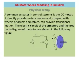
DC- MOTOR • A DC motor is an electric motor that runs on direct current (DC) electricity. In any electric motor, operation is based on simple electromagnetism. • A simple 2-pole DC electric motor (here red represents a magnet or winding with a "North" polarization, while green represents a magnet or winding with a "South" polarization). • Every DC motor has six basic parts -- axle, rotor (a.k.a., armature), stator, commutator, field magnet(s), and brushes.
MOTOR DRIVER (L293D) • Features: • Wide supply-voltage range: 4.5V to 36V • Separate input- logic supply • Internal ESD protection • Thermal shutdown • High-Noise-Immunity input • Functional Replacements for SGS L293 and SGS L293D • Output current 1A per channel (600 mA for L293D) • Peak output current 2 A per channel (1.2 A for L293D) • Output clamp diodes for Inductive Transient suppression(L293D)
DESCRIPTION • L293D is a dual H-bridge motor driver integrated circuit (IC). • In its common mode of operation, two DC motors can be driven simultaneously, both in forward and reverse direction. • The motor operations of two motors can be controlled by input logic at pins 2 & 7 and 10 & 15. • Input logic 00 or 11 will stop the corresponding motor. Logic 01 and 10 will rotate it in clockwise and anticlockwise directions, respectively. • Enable pins 1 and 9 (corresponding to the two motors) must be high for motors to start operating. When an enable input is high, the associated driver gets enabled
LIQUID CRYSTAL DISPLAY (LCD) • Most common LCDs connected to the microcontrollers are 16x2 and • 20x2 displays. • This means 16 characters per line by 2 lines and 20 characters per line • by 2 lines, respectively. • The standard is referred to as HD44780U, which refers to the controller • chip which receives data from an external source (and communicates • directly with the LCD.
LCD BACKGROUND • If an 8-bit data bus is used the LCD will require 11 data lines • (3 control lines plus the 8 lines for the data bus) • The three control lines are referred to as EN, RS, and RW • EN=Enable (used to tell the LCD that you are sending it data) • RS=Register Select (When RS is low (0), data is treated as a command) • (When RS is High(1), data being sent is text data ) • R/W=Read/Write (When RW is low (0), the data written to the LCD) • (When RW is low (0), the data reading to the LCD)
BIBILOGRAPHY • The 8051 Microcontroller and Embedded systems” by Muhammad Ali Mazidi and Janice Gillispie Mazidi , Pearson Education. • ATMEL 89S52 Data Sheets. • www.atmel.com • www.beyondlogic.org • www.wikipedia.org • www.howstuffworks.com • www.alldatasheets.com