Download
1 / 65
680 likes | 943 Views
Photovoltaic modules. Session 6. http://pveducation.org/pvcdrom/modules/hot-spot-heating. Photovoltaic modules. Session 6. PV cells can be arranged in a series configuration to form a module (panel)

E N D
Photovoltaic modules Session 6 http://pveducation.org/pvcdrom/modules/hot-spot-heating DAMON FYSON
Photovoltaic modules Session 6 PV cells can be arranged in a series configuration to form a module (panel) Modules (panels) can then be connected in parallel-series configurations to form series string and parallel arrays. When connecting cells or modules in series, they must have the same voltage rating to produce an additive voltage output, and similarly, modules must have the same current rating when connected in parallel to produce larger currents. DAMON FYSON
Photovoltaic modules Session 6 • A number of PV panels in series is termed a string • A number of strings in parallel is termed an array DAMON FYSON
Photovoltaic modules Session 6 source: http://www.nwsolarexpo.com/2011-Presentations/NW_Solar_Expo_Hernday_4.29.pdf DAMON FYSON
Photovoltaic modules Session 6 source: http://www.nwsolarexpo.com/2011-Presentations/NW_Solar_Expo_Hernday_4.29.pdf DAMON FYSON
Photovoltaic modules Session 6 source: http://www.nwsolarexpo.com/2011-Presentations/NW_Solar_Expo_Hernday_4.29.pdf DAMON FYSON
Photovoltaic modules Session 6 DAMON FYSON
Photovoltaic modules Session 6 DAMON FYSON
Photovoltaic modules Session 6 Mismatch losses are caused by the interconnection of solar cells or modules which do not have identical properties • Output determined by the solar cell with the lowest output. • example, when one solar cell is shaded remainder in the module are not, the power being generated by the "good" solar cells can be dissipated by the lower performance cell rather than powering the load. The comparison of an ideal and a non-ideal solar cell. For mismatch, the greatest difference is when the cell is driven into reverse voltage bias Source http://pveducation.org/pvcdrom/modules/mismatch-effects DAMON FYSON
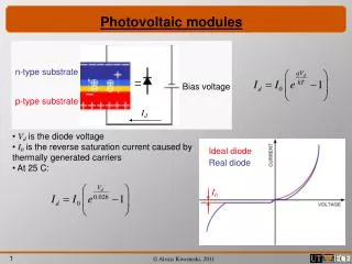
Photovoltaic modules Session 6 Theory of I-V Characterization PV cells can be modeled as a current source in parallel with a diode. When there is no light present to generate any current, the PV cell behaves like a diode. As the intensity of incident light increases, current is generated by the PV cell, as illustrated in Figure 1 DAMON FYSON
Photovoltaic modules Session 6 I-V Curves for Modules For a module or array of PV cells, the shape of the I-V curve does not change. However, it is scaled based on the number of cells connected in series and in parallel. When n is the number of cells connected in series and m is the number of cells connected in parallel and ISC and VOC are values for individual cells, the I-V curve shown in Figure 10 is produced. DAMON FYSON
Photovoltaic modules Session 6 source: http://www.nwsolarexpo.com/2011-Presentations/NW_Solar_Expo_Hernday_4.29.pdf DAMON FYSON
Photovoltaic modules Session 6 strings in parallel It = I1 +I2…… Panels in series (string) Vt = V1+V2…. DAMON FYSON
Photovoltaic modules Session 6 Understanding cell connection Current (A) • The PV module is the basic unit in a complete PV system • Understanding how the module is designed and assembled provides key understanding to designing a system • Towards this end consider the following IV characteristics of a single cell 4 Voltage (V) 0.6 DAMON FYSON
Photovoltaic modules Session 6 Current (A) • With three cells connected in series the combined characteristics are shown • Connecting the cells in series maintains the same current, only the voltage of each cell is added together 4 Voltage (V) 0.6 1.2 1.8 The combined IV characteristics of three identical cells connected in series DAMON FYSON
Photovoltaic modules Session 6 Current (A) Current (A) C • If two cells with different characteristics (dissilimar) are wired together in series, the result is shown in following figures • Series connected dissimilar cells produce an added voltage output, but series current is equal to the lowest value of the two Voltage (V) A B Voltage (V) A B The individual IV characteristics of two dissimilar cells Current (A) C D Voltage (V) A+B The combined IV characteristics of the two dissimilar cells connected in series DAMON FYSON
Photovoltaic modules Session 6 Fill Factor (slide ½) source: http://www.nwsolarexpo.com/2011-Presentations/NW_Solar_Expo_Hernday_4.29.pdf DAMON FYSON
Photovoltaic modules Session 6 source: http://www.nwsolarexpo.com/2011-Presentations/NW_Solar_Expo_Hernday_4.29.pdf DAMON FYSON
Photovoltaic modules Session 6 Commercial Modules • Solar module manufacture was 39MWs in 1994 increased to 1900MWs in 1994 • PV module production capacity increased by nearly 70% over the course of 2010, reaching nearly 30 GW by the end of the year according to IMS Research source : superhydrophobic-pv-array • Some Common standards applied to PV modules • IEC61215- Crystalline Silicon Terrestrial photovoltaic (PV ) modules • IEC61646- Crystalline Thin-film Terrestrial photovoltaic modules DAMON FYSON
Photovoltaic modules Session 6 • Five common solar panel defects • The following defects are common when testing solar panels: • Scratches on frame / glass • Excessive or uneven glue marks / Glue marks on glass • Gap between frame and glass due to poor sealing • Lower output than stated in data sheet (we require positive tolerance on each solar panel) • Lower FF than stated in requirements DAMON FYSON
Photovoltaic modules Session 6 Standard PV Panel testing parameters: With the use of the flash test, the following parameters are tested. 1. VOC (V), open-circuit voltage, The voltage output of the module is measured with the module disconnected from any load. 2. VMP (V), voltage at maximum power point, the voltage at which the module puts out the most power 3. ISC (A), the short-circuit current, Circuit Current (Isc)” and is the amount of current that the pv module supplies into a dead short. 4. Imp (A), Current at maximum power point (Imp)” and is the number of Amperes delivered by the module at its maximum power point. 5. Pm (W), Maximum Power and Maximum Power Point, power is equal to Amperes times Volts (P=IE, or Watts=Amperes X Volts). Every module has a specific point on its power curve where the product of Amps times Volts yields the greatest Wattage. This is the Maximum Power Point, the flash test takes data over the entire range of voltage and current. This way the wattage for each Current and Voltage data point can be calculated. By doing this we can find the Maximum Power Point in the sea of Current versus Voltage data. 6. FF (%), Fill Factor, the Fill Factor is defined as the maximum power produced (at MPP) divided by the product of Isc and Voc. One can see that the Fill Factor will always be less than 1. DAMON FYSON
Photovoltaic modules Session 6 DAMON FYSON
Photovoltaic modules Session 6 2011 Global Top Ten Solar Cell Manufacturer DAMON FYSON
Photovoltaic modules Session 6 2011 Global Top Ten Solar Module DAMON FYSON
Although yearly ranking is as listed above, quarterly ranking can indicate that which company can sustain particular conditions such as sever price adjustment, Government Feed- Photovoltaic modules Session 6 DAMON FYSON
Photovoltaic modules Session 6 Example of specification on a typical module 188 Watt monocrystalline panel Source: DAMON FYSON
Photovoltaic modules Session 6 Continue Example of specification on a typical module 188 Watt monocrystalline panel Source: DAMON FYSON
Photovoltaic modules Session 6 String inverter with one string String inverter grid The PV array is connected as one string and then connected to one inverter DAMON FYSON
Photovoltaic modules Session 6 Central inverter grid Several strings connected in parallel DAMON FYSON
Photovoltaic modules Session 6 The output of a single module Vmp = 17V Imp= 4A What will be the array output DAMON FYSON
Photovoltaic modules Session 6 The output of a single module Vmp = 17V Imp= 4A What will be the array output DAMON FYSON
Photovoltaic modules Session 6 source: http://www.nwsolarexpo.com/2011-Presentations/NW_Solar_Expo_Hernday_4.29.pdf DAMON FYSON
Photovoltaic modules Session 6 Electrical Protection • The PV module far right will not pass current • Because the cells in the module are connected in series and a cell is damaged(or some cells shaded) the current from the whole modules is reduced, and hence the string or array • If one cell is damaged the rest of the array can force current through it • This phenomenon is known as a Hot –spot, the cell may cause the whole array to go open circuit • The following slides shown how a diode may minimize the problem DAMON FYSON
Photovoltaic modules Session 6 • BYPASS DIODES • The module will produce less power • One or more of the cells is defective • One of more of the cells is shaded • An operating module will cause a reverse voltage to appear across the defective or shaded cell • The diode provides an alternative path for a current when a reverse voltage is present + _ DAMON FYSON
Photovoltaic modules Session 6 Hot-Spot Heating and Bypass Diodes Dissipation of power in poor cells leads to breakdown in localized regions of the cell p-n junction. An enormous power dissipation can occur in a small area, leading to local overheating, or "hot spots", which in turn leads to destructive effects, such as cell or glass cracking or melting of solder http://www.southalabama.edu/engineering/ece/faculty/akhan/Courses/EE590- Renewable/supporting%20meterial/PVDevices/pvcdrom/Ch06/Hotspot.Htm DAMON FYSON
Photovoltaic modules Session 6 source: http://www.nwsolarexpo.com/2011-Presentations/NW_Solar_Expo_Hernday_4.29.pdf DAMON FYSON
Photovoltaic modules Session 6 DAMON FYSON
Photovoltaic modules Session 6 source: http://www.nwsolarexpo.com/2011-Presentations/NW_Solar_Expo_Hernday_4.29.pdf DAMON FYSON
Photovoltaic modules Session 6 source: http://www.nwsolarexpo.com/2011-Presentations/NW_Solar_Expo_Hernday_4.29.pdf DAMON FYSON
Photovoltaic modules Session 6 DAMON FYSON
Photovoltaic modules Session 6 source: http://www.nwsolarexpo.com/2011-Presentations/NW_Solar_Expo_Hernday_4.29.pdf DAMON FYSON
Photovoltaic modules Session 6 Example of Non-Uniform Soiling DAMON FYSON
Photovoltaic modules Session 6 source: http://www.nwsolarexpo.com/2011-Presentations/NW_Solar_Expo_Hernday_4.29.pdf DAMON FYSON
Photovoltaic modules Session 6 The next 3 slides show what may happen with blocking diodes source: http://www.nwsolarexpo.com/2011-Presentations/NW_Solar_Expo_Hernday_4.29.pdf DAMON FYSON
Photovoltaic modules Session 6 source: http://www.nwsolarexpo.com/2011-Presentations/NW_Solar_Expo_Hernday_4.29.pdf DAMON FYSON
Photovoltaic modules Session 6 Bypass diodes fit a potential catastrophic event. source: http://www.nwsolarexpo.com/2011-Presentations/NW_Solar_Expo_Hernday_4.29.pdf DAMON FYSON
Photovoltaic modules Session 6 Bypass diodes allow current to pass around shaded cells and thereby reduce the voltage losses through the module. When a module becomes shaded its bypass diode becomes “forward biased” and begins to conduct current through itself. All the current greater than the shaded cell’s new short circuit current is “bypassed” through the diode, thus reducing drastically the amount of local heating at the shaded area. Source: http://www.civicsolar.com/forum/9824/what-bypass-diode DAMON FYSON
Photovoltaic modules Session 6 bypass diodes are integrated into the solar cell structure during cell fabrication. The main conclusion is that the present integral bypass diode approach automatically protects against thermal instability in both small and large arrays without the need for any other protective measures. Source: http://wenrunopto.com/product/Diode.htm DAMON FYSON
Photovoltaic modules Session 6 Source: Paul Hernday so DAMON FYSON
Photovoltaic modules Session 6 DAMON FYSON