Download
1 / 51
510 likes | 646 Views
More on Propagation. Module B. More on Propagation. Modulation Modems translate between digital devices and analog transmission lines. We will look at the processes used to modulate digital signals Multiplexing

E N D
More on Propagation Module B
More on Propagation • Modulation • Modems translate between digital devices and analog transmission lines. We will look at the processes used to modulate digital signals • Multiplexing • An important way to reduce costs is to multiplex (mix) several signals onto a transmission line • Trunk Lines • Trunk lines link the switches of carriers.
Modulation • Modulation converts an digital computer signal into a form that can travel down an ordinary analog telephone line • There are several forms of modulation • Amplitude modulation • Frequency modulation • Phase modulation • Complex modulation
The Modulation Problem • Modem accepts a digital signal from the computer • Really, binary--ones and zeros • Two voltage levels • Modem converts into waves (analog) Analog Signal Digital Signal (1101) Modem
Waves • Frequency of a wave • The number of complete cycles per second • Called Hertz • kHz, MHz, GHz, THz Frequency (Hz) Cycles in One Second
Frequency Modulation (FM) Wavelength Low Frequency (0) Wavelength High Frequency (1) 0 1 Frequency Modulation (1011) 1 1
Wavelength • Physical distance between similar points in adjacent cycles • Not independent of frequency • Frequency * wavelength = speed of light in medium • In a harp, for instance, long strings have low sounds Wavelength (meters)
Amplitude Modulation (AM) • Amplitude is the intensity of the signal • Loud or soft Amplitude (power)
Amplitude Modulation (AM) Amplitude (low) Low Amplitude (0) Amplitude (high) High Amplitude (1) Amplitude Modulation (1011)
Phase • Two signals can have the same frequency and amplitude but have different phases--be at different points in their cycles at a given moment BasicSignal 180 degrees out of phase
Phase Modulation (PM) In Phase (0) 180 degrees out of phase (1) Frequency Modulation (1011)
Phase Modulation (PM) • Human hearing is largely insensitive to phase • So harder to grasp than FM, AM • But equipment is very sensitive to phase changes • PM is used in all recent forms of modulation for telephone modems
Complex Modulation • Modern Modems Mix Phase and Amplitude In Phase 90 Degrees Out of Phase, High Amplitude High Amplitude Low Amplitude 180 Degrees Out of Phase
Complex Modulation • Baud rate: number of times the state can change per second • Usually 2,400 to 3,200 baud for telephone modems • Bits sent per possible state change depends on number of possible states • 2 b=s • b=bits per time period • s=number of possible states • In our example, 2b=8 • So b must be 3 • 3 bits are sent per time period
Complex Modulation • Bit rate = baud rate * bits/time period • bits/time period = 3, as just shown • So if the baud rate = 2,400 • Then the bit rate = 2,400 * 3 = 7,200 bits/second
Multiplexing • Multiplexing mixes the signals of different conversations over a single transmission line • To reduce costs • There are several forms of multiplexing • Time division multiplexing • Statistical time division multiplexing • Frequency division multiplexing • Multiplexing at multiple layers • Inverse multiplexing (bonding)
Why Multiplex? • Reason 1: Economies of Scale • 64 kbps lines carry a single 64 kbps signal • T1 lines can multiplex 24 such signals • Yet T1 lines cost only about 3-7* times as much as 64 kbps lines • Example: Suppose you have ten 64 kbps signals • This will require ten 64 kbps lines • But one T1 line will carry them for only 3 to 7* times the cost of a single 64 kbps line • *Textbook says 3. 3-7 is more realistic New
Why Multiplex? • Reason 2: Data transmission tends to be bursty • Uses capacity of a line only a small fraction of the time Signal A Signal B • Multiplexing allows several conversations to share a single trunk line, lowering the cost for each
Economics of Multiplexing • Cost Savings • Economies of scale in transmission lines • Multiplexing to lower costs for bursty traffic • Cost Increases • Multiplexing costs money for multiplexers/demultiplexers at the two ends • Net Savings • Usually is very high
Time Division Multiplexing • Time is divided into short periods • In each period, one frame is sent • Frame times are further divided • Each subdivision is a slot Slot Frame
Simple Time Division Multiplexing (TDM) • Several connections are multiplexed onto a line • In figure, two signals: A and B • Each connection is given one slot per frame • Guaranteed the slot • Slot is wasted if the connection does not use it • Wasteful but still brings economies of scale • Inexpensive to implement Slot not Used A B A
Statistical Time Division Multiplexing (STDM) • Still Frames and Slots • But slots are assigned as needed • Connections that need more slots get them • More efficient use of line • More expensive to implement • But STDM is now cost-effective • Multiplexers at both ends must follow the same STDM standard A B A A Frame
Frequency Division Multiplexing (FDM) • Signals are sent in different channels • Signals sent in different channels do not interfere • Brings economies of scale • Used in radio transmission A Channel Frequency B
Combining TDM and FDM • Use Simple TDM Within a Channel A B Channel Frequency
Spread Spectrum Transmission • Ways to mix signals in a channel statistically • Greater efficiency in the use of the channel • Described in Module C A B A Channel Frequency
Carrier Trunk Lines • Trunk lines are high-speed lines that connect the switches of carriers • There are several kinds of trunk lines • Optical fiber • Radio transmission • Microwave transmission • Satellite transmission • LEOs • VSATs
Optical Fiber • Thin Core of Glass • Surrounded by glass cladding • Inject light in on-off pattern for 1s and 0s • Total reflection at core-cladding boundary • Little loss with distance Cladding Core Light Source Reflection
Optical Fiber • Modes • Light entering at different angles will take different amounts of time to reach the other end • Different ways of traveling are called modes • Light modes from successive bits will begin to overlap given enough distance, making the bits unreadable Light Source Reflection
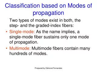
Single Mode Fiber • Single Mode Fiber is very thin • Only one mode will propagate even over fairly long distances • Expensive to produce • Expensive to install (fragile, precise alignments needed) • Used by carriers to link distant switches
Multimode Fiber • Core is thicker • Modes will appear even over fairly short distances • Must limit distances to a few hundred meters • Inexpensive to purchase and install • Dominates LANs
Graded Index Multimode Fiber • Index of fraction is not constant in core • Varies from center to edge • Reduces time delays between different modes • Signal can go farther than if core has only a single index of fraction (step index multimode fiber) • Dominates multimode fiber today
Multimode Optical Fiber and Frequency • Signal Frequency has Impact on Propagation Distance before Mode Problems Become Serious • Short Wavelength (high frequency) • Signals do not travel as far before mode problems occur • Uses the least expensive light sources • Good for LAN use within buildings • Long Wavelength (low frequency) • More expensive light sources and fiber quality • Within large buildings and between buildings
Wave Division Multiplexing • Use multiple light sources of different frequencies • Place a separate signal on each • Increases the capacity of the optical fiber
SONET/SDH • High speed optical fiber trunk system of carriers • Called SONET in the United States • Called SDH in Europe • Arranged in a Dual Ring • If a link is broken, ring is wrapped and still works • Important because broken lines are common because of construction Original Wrapped
Radio Transmission • Oscillating electron generates electromagnetic waves with the frequency of the oscillation • Many electrons must be excited in an antenna for a strong signal
Omnidirectional Antennas • Signal is transmitted as a sphere • No need to point at a receiver (or transmitter) • Attenuation with distance is very high • Used in mobile situations where dishes are impossible
Dish Antenna • Dish captures a (relatively) large amount of signal • Focuses it on a single point (which is the real antenna) • Can deal with weaker signals • You must know where to point the dish • Good in radio trunk lines, some satellite systems
Frequency Bands • Propagation Characteristics Depend on Frequency • At lower frequencies, signals bend around objects, pass through walls, and are not attenuated by rain • At higher frequencies, there is more bandwidth per major band
Major Bands • Frequency Spectrum is Divided into Major Bands • Ultra High Frequency (UHF) • Signals still bend around objects and pass through walls • Cellular telephony • Super High Frequency (SHF) • Needs line-of-sight view of receiver • Rain attenuation is strong, especially at the higher end • High channel capacity • Used in microwave, satellites
Microwave Transmission • Terrestrial (Earth-Bound) System • Limited to line-of-sight transmission • Repeaters can relay signals around obstacles Line-of-Sight Transmission Repeater
Satellite Transmission • Essentially, places repeaters in sky • Idea thought of by Sir Arthur C. Clarke • Satellite broadcasts to an area called its footprint • Uplink is to satellite; downlink is from satellite Uplink Downlink Footprint
Satellite Frequency Bands • SHF Major Band is Subdivided • Uplink/downlink frequency range (GHz) • Downlink range is always lower C Ku Ka Q/V Uplink 6 14 30 Higher Downlink 4 12 20 Higher Usage High High Growing Not Yet
GEOs • Satellite orbits at 36 km (22,300 miles) • Orbital period is 24 hours • Appears stationary in the sky • Easy to aim dishes • Very far for signals to travel • Used in trunking
LEOs • Low Earth Orbit satellites • Orbits are only 500 to 2,000 km (300 to 500 miles) • Short distance means less attenuation • But 90-minute orbit, so pointing is difficult • Fortunately, close enough for omnidirectional antenna
MEOs New • Medium Earth Orbit satellites • Orbits are 5,000 km to 15,000 km (3,000-9,000 miles) • Longer distance than LEOs means more attenuation • But longer orbit, so fewer hand-offs • Still close enough for omnidirectional antenna
VSATs • Very Small Aperture Terminal satellite system • Small dishes for remote sites (0.25 to 1 meters) • Inexpensive for remote sites • Central hub is powerful and has large dish • Satellite is powerful • Used in direct broadcast for television • Companies use VSATs to bypass carrier networks
Satellite Limitations • Limited bandwidth, so expensive • Propagation delays for GEOs • Can be bad for data transmission • More expensive than fiber for high-capacity trunk needs