Download
1 / 65
720 likes | 943 Views
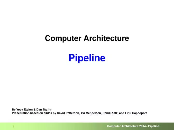
Computer Architecture Pipeline. By Yoav Etsion & Dan Tsafrir Presentation based on slides by David Patterson, Avi Mendelson, Randi Katz, and Lihu Rappoport. Pipeline idea: keep everyone busy. Pipeline: more accurately…. Expert in cutting bread. Expert in placing roast beef.

E N D
Computer ArchitecturePipeline By Yoav Etsion & Dan TsafrirPresentation based on slides by David Patterson, Avi Mendelson, Randi Katz, and Lihu Rappoport
Pipeline: more accurately… Expert in cutting bread Expert in placing roast beef Expert in placing tomatoand closing the sandwich • Pipelining elsewhere • Unix shell • grep string File | wc -l • Assembling cars • Whenever want to keepfunctional units busy
Program execution order Time lw R1, 100(R0) lw R2, 200(R0) lw R3, 300(R0) Pipeline: microarchitecture 2 4 6 8 1 0 1 2 1 4 1 6 1 8 Data Access Inst Fetch Reg Reg ALU Data Access Inst Fetch before Reg Reg ALU 8 ns Inst Fetch 8 ns . . . 8 ns
Program execution order Time lw R1, 100(R0) lw R2, 200(R0) lw R3, 300(R0) Pipeline: microarchitecture 2 4 6 8 1 0 1 2 1 4 1 6 1 8 // R1 = mem[0+100] Data Access Inst Fetch Reg Reg ALU Data Access Inst Fetch before Reg Reg ALU 8 ns fetch 100+R0 Inst Fetch decode & bringregs to ALU access mem 8 ns . . . write back result to R1 8 ns
Program execution order Program execution order Time Time lw R1, 100(R0) lw R1, 100(R0) lw R2, 200(R0) lw R2, 200(R0) lw R3, 300(R0) lw R3, 300(R0) Pipeline: microarchitecture 2 4 6 8 1 0 1 2 1 4 1 6 1 8 // R1 = mem[0+100] Data Access Inst Fetch Reg Reg ALU Data Access Inst Fetch before Reg Reg ALU 8 ns fetch 100+R0 Inst Fetch decode & bringregs to ALU access mem 8 ns . . . write back result to R1 8 ns 1 4 2 4 6 8 1 0 1 2 Data Access Inst Fetch Reg Reg ALU after Data Access Inst Fetch Reg Reg ALU 2 ns Data Access Inst Fetch Reg Reg ALU 2 ns 2 ns 2 ns 2 ns 2 ns 2 ns • Speed set by slowest component (instruction takes longer in pipeline) • First commercial use in 1985 • In Intel chips since 486 (until then, serial execution)
MIPS • Introduced in 1981 by Hennessy (of “Patterson & Hennessy”) • Idea suggested earlier, e.g., by John Cocke and friends at IBM in the 1970s, but not developed in full • MIPS = Microprocessor without Interlocked Pipeline Stages • RISC • Often used in computer architecture courses • Was very successful (e.g., inspired the Alpha ISA) • Interlocks (“without interlocks”) • Mechanisms to allow stages to indicate they are busy • E.g., ‘divide’ & ‘multiply’ required interlocks => paused other stages upstream • With MIPS, every sub-phase of all instructions fits into 1 cycle • No die area wasted on pausing mechanisms => faster cycle
Pipeline: principles • Ideal speedup = num of pipeline stages • An instruction finishes every clock cycle • Namely, IPC of an ideal pipelined machine is 1 • Increase throughput rather than reduce latency • One instruction still takes the same (or longer) • Since max speedup = num of stages &Latency determined by slowest stage, should: • Partition pipe to many stages • Balance work across stages • Shorten longest stage as much as possible
Pipeline: overheads & limitations • Can increase per-instruction latency • Due to stages imbalance • Requires more logic than serial execution • Time to “fill” pipe reduces speedupTime to “drain” pipe reduces speedup • E.g., upon interrupt or context switch • Stalls when there are dependencies
Instruction fetch Instruction Decode / register fetch Execute / address calculation Memory access Write back 0 PCSrc m u x 1 MEM/WB EX/MEM IF/ID ID/EX Add 4 Add PC Branch RegWrite Shift left 2 Read reg 1 MemWrite Instruction Read data 1 Address Read reg 2 ALUSrc ALU MemtoReg Register File zero Read data 2 Instruction Read Data 0 Write reg 1 result Address m u x m u x instruction memory Write data 1 Data Memory 0 Write Data 6 16 sign extensio 32 ALU ctrl [15-0] MemRead [20-16] 0 ALUOp m u x [15-11] 1 RegDst Pipelined CPU
0 PCSrc m u x 1 MEM/WB EX/MEM IF/ID ID/EX Add 4 Add PC Branch RegWrite Shift left 2 Read reg 1 MemWrite Instruction Read data 1 Address Read reg 2 ALUSrc ALU MemtoReg Register File zero Read data 2 Instruction Read Data 0 Write reg 1 result Address m u x m u x instruction memory Write data 1 Data Memory 0 Write Data 6 16 sign extensio 32 ALU ctrl [15-0] MemRead [20-16] 0 ALUOp m u x [15-11] 1 RegDst Pipeline: fetch bring next instructionfrom memory; 4 bytes(32 bit) per instruction when not branching,next instruction is innext word Instruction saved inregister, in preparationof next pipe stage
0 PCSrc m u x 1 MEM/WB EX/MEM IF/ID ID/EX Add 4 Add PC Branch RegWrite Shift left 2 Read reg 1 MemWrite Instruction Read data 1 Address Read reg 2 ALUSrc ALU MemtoReg Register File zero Read data 2 Instruction Read Data 0 Write reg 1 result Address m u x m u x instruction memory Write data 1 Data Memory 0 Write Data 6 16 sign extensio 32 ALU ctrl [15-0] MemRead [20-16] 0 ALUOp m u x [15-11] 1 RegDst Pipeline: decode + regs fetch • decode source reg numbers • read their values from reg file • reg IDs are 5 bits (2^5 = 32)
0 PCSrc m u x 1 MEM/WB EX/MEM IF/ID ID/EX Add 4 Add PC Branch RegWrite Shift left 2 Read reg 1 MemWrite Instruction Read data 1 Address Read reg 2 ALUSrc ALU MemtoReg Register File zero Read data 2 Instruction Read Data 0 Write reg 1 result Address m u x m u x instruction memory Write data 1 Data Memory 0 Write Data 6 16 sign extensio 32 ALU ctrl [15-0] MemRead [20-16] 0 ALUOp m u x [15-11] 1 RegDst Pipeline: decode + regs fetch decode & sign-extend immediate (from 16 bit to 32)
0 PCSrc m u x 1 MEM/WB EX/MEM IF/ID ID/EX Add 4 Add PC Branch RegWrite Shift left 2 Read reg 1 MemWrite Instruction Read data 1 Address Read reg 2 ALUSrc ALU MemtoReg Register File zero Read data 2 Instruction Read Data 0 Write reg 1 result Address m u x m u x instruction memory Write data 1 Data Memory 0 Write Data 6 16 sign extensio 32 ALU ctrl [15-0] MemRead [20-16] 0 ALUOp m u x [15-11] 1 RegDst Pipeline: decode + regs fetch decode destination reg (can be one of two, depending on op) & save in register for next stage…
0 PCSrc m u x 1 MEM/WB EX/MEM IF/ID ID/EX Add 4 Add PC Branch RegWrite Shift left 2 Read reg 1 MemWrite Instruction Read data 1 Address Read reg 2 ALUSrc ALU MemtoReg Register File zero Read data 2 Instruction Read Data 0 Write reg 1 result Address m u x m u x instruction memory Write data 1 Data Memory 0 Write Data 6 16 sign extensio 32 ALU ctrl [15-0] MemRead [20-16] 0 ALUOp m u x [15-11] 1 RegDst Pipeline: decode + regs fetch decode destination reg (can be one of two, depending on op) & save in latch for next stage… …based on the op type, next phase will determine, which reg of the two is the destination
0 PCSrc m u x 1 MEM/WB EX/MEM IF/ID ID/EX Add 4 Add PC Branch RegWrite Shift left 2 Read reg 1 MemWrite Instruction Read data 1 Address Read reg 2 ALUSrc ALU MemtoReg Register File zero Read data 2 Instruction Read Data 0 Write reg 1 result Address m u x m u x instruction memory Write data 1 Data Memory 0 Write Data 6 16 sign extensio 32 ALU ctrl [15-0] MemRead [20-16] 0 ALUOp m u x [15-11] 1 RegDst Pipeline: execute ALU computes – “R” operation (the “shift” field is missing from this illustration) reg1 reg2 to reg3 func(6bit)
0 PCSrc m u x 1 MEM/WB EX/MEM IF/ID ID/EX Add 4 Add PC Branch RegWrite Shift left 2 Read reg 1 MemWrite Instruction Read data 1 Address Read reg 2 ALUSrc ALU MemtoReg Register File zero Read data 2 Instruction Read Data 0 Write reg 1 result Address m u x m u x instruction memory Write data 1 Data Memory 0 Write Data 6 16 sign extensio 32 ALU ctrl [15-0] MemRead [20-16] 0 ALUOp m u x [15-11] 1 RegDst Pipeline: execute ALU computes – “I” operation (not branch & not load/store) reg1 imm to reg2 opcode
0 PCSrc m u x 1 MEM/WB EX/MEM IF/ID ID/EX Add 4 Add PC RegWrite Shift left 2 Read reg 1 MemWrite Instruction Read data 1 Address Read reg 2 ALUSrc ALU MemtoReg Register File zero Read data 2 Instruction Read Data 0 Write reg 1 result Address m u x m u x instruction memory Write data 1 Data Memory 0 Write Data 6 16 sign extensio 32 ALU ctrl [15-0] MemRead [20-16] 0 ALUOp m u x [15-11] 1 RegDst Pipeline: execute ALU computes – “I” operationconditional branch BEQ or BNE [ if (reg1==reg2) pc = pc+4 + (imm<<2) ] Branch? reg1 reg2 imm opcode
0 PCSrc m u x 1 MEM/WB EX/MEM IF/ID ID/EX Add 4 Add PC Branch RegWrite Shift left 2 Read reg 1 MemWrite Instruction Read data 1 Address Read reg 2 ALUSrc ALU MemtoReg Register File zero Read data 2 Instruction Read Data 0 Write reg 1 result Address m u x m u x instruction memory Write data 1 Data Memory 0 Write Data 6 16 sign extensio 32 ALU ctrl [15-0] MemRead [20-16] 0 ALUOp m u x [15-11] 1 RegDst Pipeline: execute ALU computes – “I” operationload (store is similar) ( reg2 = mem[reg1+imm] ) reg1 imm to reg2
0 PCSrc m u x 1 MEM/WB EX/MEM IF/ID ID/EX Add 4 Add PC Branch RegWrite Shift left 2 Read reg 1 MemWrite Instruction Read data 1 Address Read reg 2 ALUSrc ALU MemtoReg Register File zero Read data 2 Instruction Read Data 0 Write reg 1 result Address m u x m u x instruction memory Write data 1 Data Memory 0 Write Data 6 16 sign extensio 32 ALU ctrl [15-0] MemRead [20-16] 0 ALUOp m u x [15-11] 1 RegDst Pipeline: updating PC unconditional branch:add immediate to PC+4 (type J operation) conditional branch:depends on resultof ALU no branch:just add 4 to PC
Instruction Decode / register fetch Execute / address calculation Instruction fetch Memory access Write back ID/EX EX/MEM WB Control 0 MEM/WB WB PCSrc MEM m u x 1 WB MEM EXE IF/ID Add Add result 4 Branch PC Add RegWrite Shift left 2 Read reg 1 MemWrite Instruction Read data 1 Address Read reg 2 ALUSrc MemtoReg Register File Zero Read data 2 Instruction Read Data 0 Write reg 0 result Address ALU m u x m u x Instruction Memory Write data 1 Data Memory 1 Write Data 6 16 Sign extend 32 ALU Control [15-0] MemRead [20-16] ALUOp 0 m u x [15-11] 1 RegDst PipelinedCPU with Control
0 PCSrc m u x 1 MEM/WB EX/MEM IF/ID ID/EX 4 Add Add result 4 Branch Add RegWrite Shift left 2 Read reg 1 MemWrite Instruction Read data 1 Address Read reg 2 ALUSrc MemtoReg Register File Zero lw Read data 2 Instruction Read Data PC 0 Write reg 1 result Address ALU m u x m u x Instruction Memory 4 Write data 1 Data Memory 0 Write Data 6 16 Sign extend 32 ALU Control [15-0] MemRead [20-16] 0 ALUOp m u x [15-11] 1 RegDst Pipeline Example: cycle 1 0 lw R10,9(R1) 4 sub R11,R2,R3 8 and R12,R4,R512 or R13,R6,R7
0 PCSrc m u x 1 MEM/WB EX/MEM IF/ID ID/EX 4 8 Add Add result 4 lw Branch Add RegWrite Shift left 2 Read reg 1 MemWrite Instruction [R1] Read data 1 Address Read reg 2 ALUSrc MemtoReg sub Register File Zero Read data 2 Instruction Read Data PC 0 Write reg 1 result Address ALU m u x m u x Instruction Memory 8 Write data 1 Data Memory 0 Write Data 6 16 Sign extend 32 ALU Control [15-0] 9 MemRead [20-16] 10 0 ALUOp m u x [15-11] 1 RegDst Pipeline Example: cycle 2 0 lw R10,9(R1) 4 sub R11,R2,R3 8 and R12,R4,R512 or R13,R6,R7
0 PCSrc m u x 1 MEM/WB EX/MEM IF/ID ID/EX 4 8 12 Add Add result 4 sub lw Branch Add RegWrite Shift left 2 Read reg 1 MemWrite Instruction [R2] Read data 1 Address Read reg 2 ALUSrc MemtoReg and Register File Zero PC [R3] Read data 2 Instruction Read Data [R1]+9 0 Write reg 1 result Address 12 ALU m u x m u x Instruction Memory Write data 1 Data Memory 0 Write Data 6 16 Sign extend 32 ALU Control [15-0] MemRead [20-16] 0 ALUOp m u x 10 [15-11] 11 1 RegDst Pipeline Example: cycle 3 0 lw R10,9(R1) 4 sub R11,R2,R3 8 and R12,R4,R512 or R13,R6,R7
Pipeline Example: cycle 4 0 PCSrc m u x 1 MEM/WB EX/MEM IF/ID ID/EX 4 8 16 12 Add Add result 4 and sub lw Branch Add RegWrite Shift left 2 Read reg 1 MemWrite Instruction [R4] Read data 1 Address Read reg 2 ALUSrc MemtoReg or Register File Zero PC [R5] Read data 2 Instruction Read Data [R2]-[R3] 0 Write reg 1 result Address 16 ALU m u x m u x Instruction Memory Data from memory address [R1]+9 Write data 1 Data Memory 0 Write Data 6 16 Sign extend 32 ALU Control [15-0] MemRead [20-16] 0 ALUOp m u x 11 10 [15-11] 12 1 RegDst 0 lw R10,9(R1) 4 sub R11,R2,R3 8 and R12,R4,R512 or R13,R6,R7
R e g I M R e g D M I M D M R e g R e g I M D M R e g R e g I M D M R e g R e g I M D M R e g R e g Structural Hazard • Two instructions attempt to use same resource simultaneously • Problem: register-file accessed in 2 stages • Write during stage 5 (WB) • Read during stage 2 (ID) => Resource (RF) conflict • Solution • Split stage into two sub-stages • Do write in first half • Do reads in second half • 2 read ports, 1 write port (separate)
R e g I M R e g D M I M D M R e g R e g I M D M R e g R e g I M D M R e g R e g I M D M R e g R e g Structural Hazard • Problem: memory accessed in 2 stages • Fetch (stage 1), when reading instructions from memory • Memory (stage 4), when datais read/written from/tomemory • Princeton architecture • Solution • Split data/inst. Memories • Harvard architecture • Today, separate instruction cache and data cache
Data Dependencies • When two instructions access the same register • RAW: Read-After-Write • True dependency • WAR: Write-After-Read • Anti-dependency • WAW: Wrtie-After-Write • False-dependency • Key problem with regular in-orderpipelines is RAW • We will also learn about out-of-order pipelines
Time (clock cycles) C C 1 C C 2 C C 3 C C 4 C C 5 C C 6 C C 7 C C 8 C C 9 Program execution order 10 – 2 0 Value of R2 0 10 10 10 -20 -20 -20 -20 R e g I M R e g D M I M D M R e g R e g I M D M R e g R e g I M D M R e g R e g I M D M R e g R e g Data Dependencies • Problem with starting next instruction before first is finished • dependencies that “go backward in time” are data hazards sub R2, R1, R3 and R12,R2, R5 or R13,R6, R2 add R14,R2, R2 sw R15,100(R2)
I I I M M M bubble bubble bubble bubble bubble bubble bubble bubble bubble bubble bubble bubble I M D M R e g R e g I M D M R e g R e g I M D M R e g R e g I M D M R e g R e g RAW Hazard: HW Solution 1 - Add Stalls • Let the hardware detect hazard and add stalls if needed Time (clock cycles) C C 1 C C 2 C C 3 C C 4 C C 5 C C 6 C C 7 C C 8 C C 9 Program execution order 10 0 – 2 0 Value of R2 10 10 10 -20 -20 -20 -20 sub R2, R1, R3 stall stall stall and R12,R2, R5 or R13,R6, R2 add R14,R2, R2 sw R15,100(R2) R e g I M R e g D M Problem: slow! Solution: forwarding whenever possible
X X X X – 20 X X X X RAW Hazard: HW Solution 2 - Forwarding • Use temporary results, don’t wait for them to be written to the register file • register file forwarding to handle read/write to same register • ALU forwarding Time (clock cycles) C C 1 C C 2 C C 3 C C 4 C C 5 C C 6 C C 7 C C 8 C C 9 10 – 2 0 0 Value of R2 10 10 10 -20 -20 -20 -20 Value EX/MEM X X X – 20 X X X X X Program execution order Value MEM/WB sub R2, R1, R3 and R12,R2, R5 or R13,R6, R2 add R14,R2, R2 sw R15,100(R2) I M R e g D M R e g I M R e g D M R e g I M R e g D M R e g I M R e g D M R e g I M R e g D M R e g
IF/ID MEM/WB ID/EX EX/MEM WB Control M WB M EX WB EX/MEM.RegWrite 0 m u x A MEM/WB.RegWrite 1 Instruction Register File 2 Instruction Memory Data Memory ALU PC 1 m u x 0 m u x B 0 1 2 IF/ID.Rs Rs IF/ID.Rt Rt IF/ID.Rt 0 Rt EX/MEM.Rd m u x IF/ID.Rd Rd 1 Forwarding Unit MEM/WB.Rd Forwarding Hardware
IF/ID MEM/WB ID/EX EX/MEM WB Control M WB M EX WB EX/MEM.RegWrite 0 m u x A MEM/WB.RegWrite 1 Instruction Register File 2 Instruction Memory Data Memory ALU PC 1 m u x 0 m u x B 0 1 2 IF/ID.Rs Rs IF/ID.Rt Rt IF/ID.Rt 0 Rt EX/MEM.Rd m u x IF/ID.Rd Rd 1 Forwarding Unit MEM/WB.Rd Forwarding Hardware • Added 2 mux units before ALU • Each mux gets 3 inputs, from: • Prev stage (ID/EX) • Next stage (EX/MEM) • The one after (MEM/WB) • Forward unit tells the 2 mux units which input to use
Forwarding Control • EX Hazard: • if (EX/MEM.RegWriteand (EX/MEM.WriteReg = ID/EX.ReadReg1)) thenALUSelA = 1 • if (EX/MEM.RegWriteand(EX/MEM.WriteReg = ID/EX.ReadReg2)) thenALUSelB = 1 • MEM Hazard: • if (not A and MEM/WB.RegWrite (MEM/WB.WriteReg = ID/EX.ReadReg1)) thenALUSelA = 2 • if (not B and MEM/WB.RegWriteand (MEM/WB.WriteReg = ID/EX.ReadReg2)) thenALUSelB = 2
Forwarding Control • EX Hazard: • if (EX/MEM.RegWriteand (EX/MEM.WriteReg = ID/EX.ReadReg1)) thenALUSelA = 1 • if (EX/MEM.RegWriteand(EX/MEM.WriteReg = ID/EX.ReadReg2)) thenALUSelB = 1 • MEM Hazard: • if (not A and MEM/WB.RegWrite (MEM/WB.WriteReg = ID/EX.ReadReg1)) thenALUSelA = 2 • if (not B and MEM/WB.RegWriteand (MEM/WB.WriteReg = ID/EX.ReadReg2)) thenALUSelB = 2 If, in memory stage, we’re writing the output to a register And the reg we’re writing to also happens to be inp_reg1 for the execute stage Then mux_A should select inp_1,namely, the ALU should feed itself
IF/ID MEM/WB ID/EX EX/MEM WB Control M WB M EX WB [R10] 0 sub lw m u x 1 Instruction and Register File 2 Instruction Memory Data Memory [R2]-[R3] ALU PC 1 Data from memory address [R1]+9 m u x [R11] 0 m u x 0 1 2 IF/ID.Rs Rs 10 IF/ID.Rt Rt 11 IF/ID.Rt 0 Rt EX/MEM.Rd m u x 10 11 IF/ID.Rd Rd 12 1 Forwarding Unit MEM/WB.Rd Forwarding Hardware Example: Bypassing From EX to Src1 and From WB to Src2 load op => read from “1” lw R11,9(R1) sub R10,R2, R3and R12,R10,R11
IF/ID MEM/WB ID/EX EX/MEM WB Control M WB M EX WB [R11] 0 xxx sub m u x 1 Instruction and Register File 2 Instruction Memory Data Memory ALU PC 1 [R2]-[R3] m u x [R10] 0 m u x 0 1 2 IF/ID.Rs Rs 10 IF/ID.Rt Rt 11 IF/ID.Rt 0 Rt EX/MEM.Rd m u x 10 IF/ID.Rd Rd 12 1 Forwarding Unit MEM/WB.Rd Forwarding Hardware Example #2: Bypassing From WB to Src2 not load op => read from “0” sub R10,R2, R3 xxxand R12,R10,R11
Program execution order Can't always forward (stall inevitable) • “load” op can cause “un-forwardable” hazards • load value to R • In the next instruction, use R as input Time (clock cycles) C C 1 C C 2 C C 3 C C 4 C C 5 C C 6 C C 7 C C 8 C C 9 lw R2, 30(R1) and R12,R2, R5 or R13,R6, R2 add R14,R2, R2 sw R15,100(R2) R e g I M D M R e g I M R e g D M R e g I M R e g D M R e g I M R e g D M R e g I M D M R e g R e g • A bigger problem in longer pipelines
Hazard Detection (Stall) Logic if ( (ID/EX.RegWrite) and (ID/EX.opcode == lw) and ( (ID/EX.WriteReg == IF/ID.ReadReg1) or (ID/EX.WriteReg == IF/ID.ReadReg2) ) then stall IF/ID
ID/EX.MemRead Hazard Detection Unit: Scoreboard IF/ID MEM/WB ID/EX EX/MEM WB IF/ID Write Control M WB 0 PC Write m u x M EX WB 0 1 0 m u x 1 Instruction Register File 2 Instruction Memory Data Memory ALU PC 1 m u x 0 m u x 0 1 2 IF/ID.Rs Rs IF/ID.Rt Rt IF/ID.Rt 0 Rt EX/MEM.Rd m u x IF/ID.Rd Rd 1 Forwarding Unit MEM/WB.Rd ID/EX.Rt Forwarding + Hazard Detection Unit
Compiler scheduling helps avoid load hazards (when possible) Example: code for (assume all variables are in memory): a = b + c; d = e – f; Slow code LW Rb,b LW Rc,c Stall ADD Ra,Rb,Rc SW a,Ra LW Re,e LW Rf,f Stall SUB Rd,Re,Rf SW d,Rd Instruction order can be changed as long as correctness is kept (no dependencies violated) Fast code LW Rb,b LW Rc,c LW Re,e ADD Ra,Rb,Rc LW Rf,f SW a,Ra SUB Rd,Re,Rf SW d,Rd
Branch, but where? • The decision to branch happens deep within the pipeline • Likewise, the target of the branch becomes known deep within the pipeline • How does this effect the pipeline logic? • For example…
0 PCSrc m u x 1 MEM/WB EX/MEM IF/ID ID/EX 8 12 Add Add result 4 and beq Branch Add RegWrite Shift left 2 Read reg 1 MemWrite Instruction R4 - PC Read data 1 Address Read reg 2 ALUSrc 12 MemtoReg Register File Zero R5 Read data 2 Instruction Read Data Write reg 0 0 result Address ALU m u x m u x Instruction Memory Write data 1 Data Memory 1 Write Data 6 16 Sign extend 32 ALU Control [15-0] 27 MemRead [20-16] 0 ALUOp m u x [15-11] 1 RegDst Executing a BEQ Instruction (i) BEQ R4, R5, 27→ if (R4-R5=0) then PC PC+4+SignExt(27)*4 ; else PC PC+4 Assume this program state 0 or 4 beq R4, R5, 27 8 and12 sw 16 sub
0 PCSrc m u x 1 MEM/WB EX/MEM IF/ID ID/EX 8 12 Add Add result 4 and beq Branch Add RegWrite Shift left 2 Read reg 1 MemWrite Instruction R4 - PC Read data 1 Address Read reg 2 ALUSrc 12 MemtoReg Register File Zero R5 Read data 2 Instruction Read Data Write reg 0 0 result Address ALU m u x m u x Instruction Memory Write data 1 Data Memory 1 Write Data 6 16 Sign extend 32 ALU Control [15-0] 27 MemRead [20-16] 0 ALUOp m u x [15-11] 1 RegDst Executing a BEQ Instruction (i) BEQ R4, R5, 27→ if (R4-R5=0) then PC PC+4+SignExt(27)*4 ; else PC PC+4 • We know: • Values of registers • We don’t know: • If branch will be taken • What is its target 0 or 4 beq R4, R5, 27 8 and12 sw 16 sub
0 8+SignExt(27)*4 PCSrc m u x 1 MEM/WB EX/MEM IF/ID ID/EX 16 12 Add Add result 4 Branch Add RegWrite Shift left 2 beq sw and Read reg 1 MemWrite Instruction - Read data 1 Address PC Read reg 2 R4-R5=0 ALUSrc MemtoReg Register File Zero 16 Read data 2 Instruction Read Data 0 Write reg 0 result Address ALU m u x m u x Instruction Memory Write data 1 Data Memory 1 Write Data 6 16 Sign extend 32 ALU Control [15-0] MemRead [20-16] 0 ALUOp m u x [15-11] 1 RegDst Executing a BEQ Instruction (ii) BEQ R4, R5, 27→ if (R4-R5=0) then PC PC+4+SignExt(27)*4 ; else PC PC+4 …Now we know, but only in next cycle will this effect PC Calculate branch target 0 or 4 beq R4, R5, 27 8 and12 sw 16 sub Calculate branch condition = compute R4-R5 & compare to 0
0 8+SignExt(27)*4 PCSrc m u x 1 MEM/WB EX/MEM IF/ID ID/EX 16 Add 20 Add result 4 Branch Add RegWrite Shift left 2 beq sub sw and Read reg 1 MemWrite Instruction Read data 1 Address PC Read reg 2 ALUSrc MemtoReg Register File Zero 20 or 116 Read data 2 Instruction Read Data 0 Write reg 0 result Address ALU m u x m u x Instruction Memory Write data 1 Data Memory 1 Write Data 6 16 Sign extend 32 ALU Control [15-0] MemRead [20-16] 0 ALUOp m u x [15-11] 1 RegDst Executing a BEQ Instruction (iii) BEQ R4, R5, 27→ if (R4-R5=0) then PC PC+4+SignExt(27)*4 ; else PC PC+4 Finally, if taken, branch sets the PC 0 or 4 beq R4, R5, 27 8 and12 sw 16 sub
PC R R R e e e g g g I I I M M M R R R e e e g g g D D D M M M R e g I M R e g D M PC PC PC PC R e g I M R e g D M Control Hazard on Branches Beq Outcome: The 3 instructions following the branch are in the pipeline even if branch is taken! And sw sub Inst from target