Download
1 / 57
570 likes | 769 Views
Chapters 8 Storage, Networks, and Other Peripherals. Outline. 8.1 Introduction 8.2 Disk Storage and Dependability 8.3 Networks 8.4 Buses and Other Connections between Processors, Memory, and I/O Devices 8.5 Interfacing I/O Devices to the Processor, Memory, and Operating System

E N D
Outline • 8.1 Introduction • 8.2 Disk Storage and Dependability • 8.3 Networks • 8.4 Buses and Other Connections between Processors, Memory, and I/O Devices • 8.5 Interfacing I/O Devices to the Processor, Memory, and Operating System • 8.6 I/O Performance Measures: Examples from Disk and File Systems • 8.7 Designing an I/O System • 8.8 Real Stuff: A Digital Camera • 8.9 Fallacies and Pitfalls • 8.10 Concluding Remarks • 8.11 Historical Perspective and Further Reading
Keywords • I/O requests Reads or writes to I/O devices
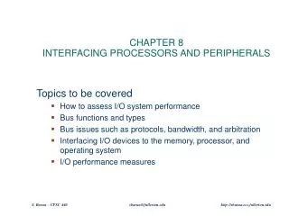
Interfacing Processors and Peripherals • I/O Design affected by many factors (expandability, resilience) • Performance: — access latency — throughput — connection between devices and the system — the memory hierarchy — the operating system • A variety of different users (e.g., banks, supercomputers, engineers)
I/O • Important but neglected “The difficulties in assessing and designing I/O systems have often relegated I/O to second class status” “courses in every aspect of computing, from programming to computer architecture often ignore I/O or give it scanty coverage” “textbooks leave the subject to near the end, making it easier for students and instructors to skip it!” • GUILTY! — we won’t be looking at I/O in much detail — be sure and read Chapter 8 in its entirety. — you should probably take a networking class!
I/O Devices • Very diverse devices — behavior (i.e., input vs. output) — partner (who is at the other end?) — data rate
Keywords • NonvolatileStorage device where data retains its value even when power is removed. • TrackOne of thousands of concentric circles that makes up the surface of a magnetic disk. • SectorOne of the segments that make up a track on a magnetic disk; a sector is the smallest amount of information that is read or written on a disk. • Seek The process of positioning a read/write head over the proper track on a disk. • Rotation latencyAlso called delay. The time required for the desired sector of a disk to rotate under the read/write head; usually assumed to be half the rotation time. • Small computer systems interface (SCSI)A bus used as a standard for I/O devices.
Keywords • Redundant arrays of inexpensive disks (RAID)An organization of disks that uses an array of small and inexpensive disks so as to increase both performance and reliability. • Striping Allocation of logically sequential blocks to separate disk to allow higher performance than a single disk can deliver. • Mirroring Writing the identical data to multiple disks to increase data availability. • Protection groupThe group of data disks or blocks that share a common check disk or block. • Hot swappingReplacing a hardware component while the system is running. • Standby sparesReserve hardware resources that can immediately take the place of a failed component.
I/O Example: Disk Drives • To access data: — seek: position head over the proper track (3 to 14 ms. avg.) — rotational latency: wait for desired sector (.5 / RPM) — transfer: grab the data (one or more sectors) 30 to 80 MB/sec
Disk Read Time • Q:What is the average time to read or write a 512-byte sector for a typical disk rotating at 10,000 RPM? The advertised average seek time is 6 ms, the transfer rate is 50 MB/sec, and the controller overhead is 0.2 ms. Assume that the disk is idle so that there is no waiting time. • A: If the measured average seek time is 25% of the advertised average time. The answer is 1.5ms + 3.0ms + 0.01ms + 0.2ms = 4.7ms
Figure 8.3 Six magnetic disks, varying in diameter from 14 inches down to 1.8 inches.
Figure 8.4 Characteristics of three magnetic disks by a single manufacturer in 2004.
Figure 8.6 RAID for an example of four data disks showing extra check disks per RAID level and companies that use each level.
Figure 8.8 Block-interleaved parity (RAID 4) versus distributed block-interleaved parity (RAID 5)
Networks are growing in popularity over time, and unlike other I/O devices, there are many books and courses on them. For readers who have not taken courses or read books on networking, Section 8.3 on the CD gives a quick overview of the topics and terminology, including internetworking, the OSI model, protocol families such as TCP/IP, long-haul networks such as ATM, local area networks such as Ethernet, and wireless networks such as IEEE 802.11.
8.4 Buses and Other Connections between Processors, Memory, and I/O Devices
Keywords • Bus transactionA sequence of bus operations that includes a request and may includes a request and may include a response, either of which may carry data. A transaction is initiated by a single request and may take many individual bus operations. • Processor-memory busA bus that connects processor and memory and that is short, generally high speed, and matched to the memory system so as to maximize memory-processor bandwidth. • Backplane busA bus that is designed to allow processors, memory. And I/O devices to coexist on a single bus. • Synchronous busA bus that includes a clock in the control lines and a fixed protocol for communicating that is relative to the clock. • Asynchronous bus A bus that uses a handshaking protocol for coordinating usage rather than a clock; can accommodate a wide variety of devices of differing speeds.
Keywords • Handshaking protocolA series of steps used to coordinate asynchronous bus transfers in which the sender and receiver proceed to the next step only when both parties agree that the current step has been completed. • Split transaction protocolA protocol in which the bus is released during a bus transaction while the requester is waiting for the data to be transmitted, which frees the bus for access by another requester.
I/O Example: Buses • Shared communication link (one or more wires) • Difficult design: — may be bottleneck — length of the bus — number of devices — tradeoffs (buffers for higher bandwidth increases latency) — support for many different devices — cost • Types of buses: — processor-memory (short high speed, custom design) — backplane (high speed, often standardized, e.g., PCI) — I/O (lengthy, different devices, e.g., USB, Firewire) • Synchronous vs. Asynchronous — use a clock and a synchronous protocol, fast and small but every device must operate at same rate and clock skew requires the bus to be short — don’t use a clock and instead use handshaking
I/O Bus Standards • Today we have two dominant bus standards:
Figure 8.10 The asynchronous handshaking protocol consists of seven steps to read a word from memory and receive it in an I/O device.
Figure 8.11 Organization of the I/O system on a Pentium 4 PC using the intel 875 chip
8.5 Interfacing I/O Devices to the Processor, Memory, and Operating System
Keywords • Memory-mapped I/OAn I/O scheme in which portions of address space are assigned to I/O devices and reads and writes to those addresses are interpreted as commands to the I/O device. • I/O instructions A dedicated instruction that is used to give a command to an I/O device and that specifies both the device number and the command word (or the location of the command word in memory). • Polling The process of periodically checking the status of an I/O device to determine the need to service the device. • Interrupted-driven I/O An I/O scheme that employs interrupts to indicate to the processor that an I/O device needs attention. • Direct memory access (DMA) A mechanism that provides a device controller the ability to transfer data directly to or from the memory without involving the processor. • Bus master A unit on the bus that can initiate bus requests.
Other important issues • Bus Arbitration: — daisy chain arbitration (not very fair) — centralized arbitration (requires an arbiter), e.g., PCI — collision detection, e.g., Ethernet • Operating system: — polling — interrupts — direct memory access (DMA) • Performance Analysis techniques: — queuing theory — simulation — analysis, i.e., find the weakest link (see “I/O System Design”) • Many new developments
8.6 I/O Performance Measures:Examples from Disk and File Systems
Keywords • Transaction processingA type of application that involves handling small short operations (called transactions) that typically require both I/O and computation. Transaction processing applications typically have both response time requirements and a performance measurement based on the throughput of transactions. • I/O ratePerformance measure of I/Os per unit time. Such as reads per second. • Data ratePerformance measure of bytes per unit time, such as GB/second.
Impact of I/O on system performance • Q:Suppose we have a benchmark that executes in 100 seconds of elapsed time, where 90 seconds is CPU time and the rest is I/O time. If CPU time improves by 50% per year for the next five years but I/O time doesn’t improve, how much faster will our program run at the end of five years? A: • We know that Elapsed time = CPU time + I/O time 100 = 90 + I/O time I/O time = 10 seconds The new CPU times and the resulting elapsed times are computed in the following table: <next page>
The improvement in CPU performance over five years is However, the improvement in elapsed time is only and the I/O time has increased from 10% to 45% of the elapsed time.
I/O System Design • Q:Consider the following computer system: • A CPU that sustain 3 billion instructions per second and averages 100,000 instruction in the operating system per I/O operation • A memory backplane bus capable of sustaining a transfer rate of 1000 MB/sec • SCSI Ultra320 controllers with a transfer rate of 320 MB/sec and accommodating up to 7 disks • Disk drives with a read/write bandwidth of 75 MB/sec and an average seek plus rotational latency of 6 ms. If the workload consists of 64 KB reads (where the block is sequential on a track) and the user program needs 200,000 instructions per I/O operation, find the maximum sustainable I/O rate and the number of disks and SCSI controllers required. Assume that the reads can always be done on an idle disk if one exists (i.e., ignore disk conflicts).
A: The maximum number of disks per SCSI bus is 7, which won’t saturate this bus. This means we will need 69/7, or 10 SCSI buses and controllers.
Figure 8.14 The Sanyo VPC-SX500 with Flash memory card and IBM Microdrive.
Figure 8.15 Characteristics of three storage alternatives for digital cameras.
Figure 8.16 The system on a chip (SOC) found in Sanyo digital cameras.
Fallacies and Pitfalls • Fallacy: the rated mean time to failure of disks is 1,200,000 hours, so disks practically never fail. • Fallacy: magnetic disk storage is on its last legs, will be replaced. • Fallacy: A 100 MB/sec bus can transfer 100 MB/sec. • Pitfall: Moving functions from the CPU to the I/O processor, expecting to improve performance without analysis.
Multiprocessors • Idea: create powerful computers by connecting many smaller ones good news: works for timesharing (better than supercomputer) bad news: its really hard to write good concurrent programs many commercial failures