Download
1 / 33
340 likes | 536 Views
The FEA Code of LASCAD. Konrad Altmann LAS-CAD GmbH.

E N D
The FEA Code of LASCAD Konrad Altmann LAS-CAD GmbH Heat removal and thermal lensing constitute key problems for the design of laser cavities for solid-state lasers (SSL, DPSSL etc.). To compute thermal effects in laser crystals LASCAD uses a Finite Element code specifically developed to meet the demands of laser simulation.
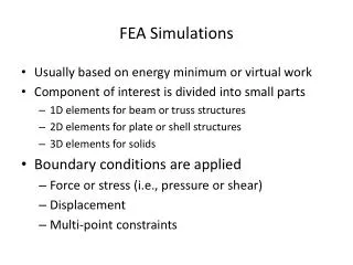
The thermal analysis is carried through in three • steps: • Determination of heat load distribution, • Solution of the 3-D differential equations of heat conduction, • Solution of the differential equation of structural deformation.
Differential Equation of Heat Conduction Differential equations of conduction of heat κ coefficient of thermal conductivity T temperature Q heat load distribution Dirichlet boundary condition Surface kept on constant temperature
Boundary condition for fluid cooling hf film coefficient Ts surface temperature
Differential Equations of Structural Deformation Strain-stress relation σi,j stress tensor αi coefficient of thermal expansion E elastic modulus εi,j strain tensor, ui displacement
To solve these differential equations, a finite element discretization is applied on a semi-unstructured grid. This terminus means that the grid has regular and equidistant structure inside the crystal which is fiited irregularily to the boundaries of the body. See for instance the case of a rod
Semi-unstructured meshing has a series of useful properties: • The structured grid inside the body allows for efficient use of the results with optical codes, for instance easy interpolation, • Meshing can be carried through automatically, • The grids can be stretched in x-, y-, and z-direction, • High accuracy can be achieved by the use of small mesh size, • The superconvergence of the gradient inside the domain leads to an accurate approximation of stresses.
Computation of Heat Load Distribution Computation of heat load can be carried through in two ways: • Use of analytical approximations • Numerical computation by the use of ray tracing codes. LASCAD does not have its own ray tracing code, but has interfaces to the well known and reliable codes ZEMAX and TracePro.
For the analytical approximation of the heat load supergaussian functions are used. As an example I am discussing the case of an end pumped rod with a pump beam being focussed from the left end into the rod.
In this case the absorbed pump power density can be described as follows P incident pump power α absorption coefficient z distance from entrance plane β heat efficiency Cx, Cy normalization constants SGX, SGY supergaussian exponents SG=2 common gaussian, SG ∞ tophat wx, wy local spot sizes
Local spot sizes wx and wy are given by and θ divergence angle f distance from entrance plane The pump beam can be defined astigmatic, for instance common gaussian the x direction and tophat in y direction. Also pumping from both ends is possible.
With the above equations the heat load in end pumped crystals can be approximated very closely. Similarly, side pumping of a cylindrical rod can be described by the use of analytical approximations as will be shown now.
Side Pumped Rod Diode Crystal Water Flow Tube Reflector
In this case the propagation of the pump beam in a plane perpendicular to the crystal axis is described by the Gaussian algorithm. It is assumed that the transformation of the beam traversing the different cylindrical surfaces can be described by appropriate matrices. This issue is described in more detail in Tutorial No.2.
Two important parameters have to adjusted to get the correct heat load αabsorption coefficient of the pump light βheat efficiency of the laser material
By the use of the absorption coefficient the atten-uation of the pump light can be described by the use of an exponential law The absorption coefficient can determined experimen-tally by measuring the transmission through a plate of the laser material. Numerically the absorption coefficient can be deter-mined by computing the overlap integral of the emission spectrum of the laser diode and the absorption spectrum of the laser material
Emission spectra of high power laser diode P1202 of Coherent, Inc. for different values of diode current at constant temperature 20° C.
The heat efficiency β of the laser material, also called fractional thermal load, is the relative amount of the absorbed pump power density which is converted into heat load. The heat efficiency is defined by where Pabs is the absorbed pump power and Pheat is the generated thermal load.
The heat efficiency β of the laser material depends on quantummechanical properties of the laser material and can determined by the following equation ηppump efficiency (fraction of absorbed pump photons which contribute to the population of the upper laser level) ηr efficiency of spontaneous emission ηl efficiency of stimulated emission λppump wave length λlwave length of lasing transition λf averaged fluorescence wave length
Neglecting the difference between λl and λf in a rough approximation the above expression for the heat efficiency can be written as This equation shows that the heat efficiency mainly is determined by the ratio λp/λl .
For important laser materials values for the heat efficiency can be found in the literature. For instance, for Nd:YAG the value 0.3 usually is found and delivers reliable results. This value has been checked in cooperation with German universities, and has been delivering very good agreement with measurements for the thermal lens in many cases. Since for Yb:YAG the lower laser level is close to ground level the heat efficiency is smaller. A value of 0.11 turned out to deliver good agreement with measurements for the thermal lens.
As mentioned in the paper "introduction and overview.ppt" measurements carried through by the Solid-State Lasers and Application Team (ELSA) Centre Université d'Orsay, France delivered good agreement with LASCAD simulation.
Numerical Computation of Heat Load Distribution Analytical approximations for the absorbed pump power density are not always sufficient. There are situations, for instance scattering surfaces of the crystal, where numerical computation by the use of a ray tracing code if necessary. For this purpose LASCAD has interfaces to the ray tracing codes codes ZEMAX and TracePro.
Both programs can compute the absorbed pump power using a discretization of the crystal volume into a rectangular voxels. The pump power absorbed absorbed in each voxel is written to a 3D data set which can be used as input for LASCAD which is interpolating the data with respect to the grid used by the FEA code.
On the LASCAD CD-ROM the following example can be found for a flashlamp pumped rod analyzed by the use of ZEMAX.
After 3D interpolation the heat load shown below is obtained with LASCAD
Another interesting configuration has been analyzed by one of our customers by the use of TracePro. Here you can see a crystal rod which is embedded in a block of copper. The pump light is coming from a diode bar is entering through this is slot.
Computation of Stress Intensity Since the individual components of the stress tensor to not deliver sufficient information concerning fraction problems, the stress intensity is being computedwhich is defined by Here are the components of the stress tensor with respect to the principal axis. The stress tensor is a useful parameter to control cracking limits.