Download
1 / 31
350 likes | 577 Views
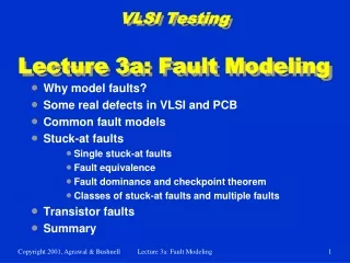
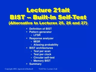
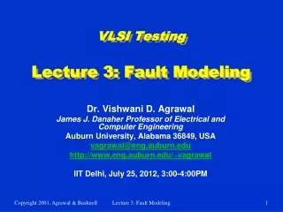
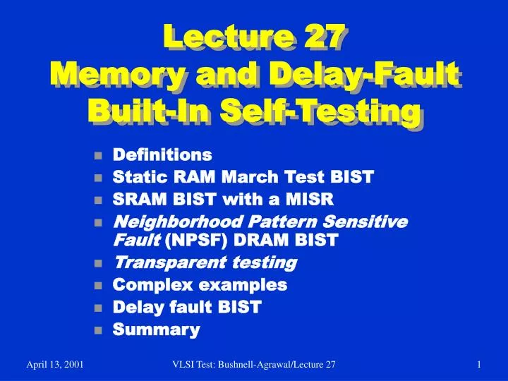
Lecture 27 Memory and Delay-Fault Built-In Self-Testing. Definitions Static RAM March Test BIST SRAM BIST with a MISR Neighborhood Pattern Sensitive Fault (NPSF) DRAM BIST Transparent testing Complex examples Delay fault BIST Summary. Definitions.

E N D
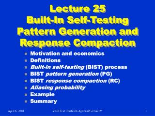
Lecture 27Memory and Delay-Fault Built-In Self-Testing • Definitions • Static RAM March Test BIST • SRAM BIST with a MISR • Neighborhood Pattern Sensitive Fault (NPSF) DRAM BIST • Transparent testing • Complex examples • Delay fault BIST • Summary VLSI Test: Bushnell-Agrawal/Lecture 27
Definitions • Concurrent BIST – Memory test that happens concurrently with normal system operation • Transparent testing – Memory test that is non-concurrent, but preserves the original memory contents from before testing began VLSI Test: Bushnell-Agrawal/Lecture 27
LFSR and Inverse Pattern LFSR • NOR gate forces LFSR into all-0 state • Get all 2n patterns • Normal LFSR: G (x) = x3 + x + 1 • Inverse LFSR: G (x) = x3 + x2 + 1 VLSI Test: Bushnell-Agrawal/Lecture 27
0 0 0 0 M U X M U X M U X M U X D D D Q Q Q 1 1 1 1 Up / Down LFSR • Preferred memory BIST pattern generator • Satisfies March test conditions X0 X1 X2 Up/Down VLSI Test: Bushnell-Agrawal/Lecture 27
Up Counting 000 100 110 111 011 101 010 001 Down Counting 000 001 010 101 011 111 110 100 Up / Down LFSR Pattern Sequences VLSI Test: Bushnell-Agrawal/Lecture 27
Mutual Comparator • Test 4 or more memory arrays at same time: • Apply same test commands & addresses to all 4 arrays at same time • Assess errors when one of the di (responses) disagrees with the others VLSI Test: Bushnell-Agrawal/Lecture 27
Mutual Comparator System • Memory BIST with mutual comparator • Benefit: Need not have good machine response stored or generated VLSI Test: Bushnell-Agrawal/Lecture 27
Parallel Memory BIST VLSI Test: Bushnell-Agrawal/Lecture 27
Parallel Memory March C • Add MUX to inputs of write drivers: • Selects normal data input or left neighbor sense amplifier output • Creates shift register during self-test • Generalize any March test to test n-bit words in array rows • (x)n means repeat x operations n times • Example: March Cn • { (w0)n (r0, w0)n; (r0, w1)n (r1, w1)n; (r1, w0)n (r0, w0)n; (r0, w1)n (r1, w1)n; (r1, w0)n (r0, w0)n; (r0, w0)n (r0, w0)n} VLSI Test: Bushnell-Agrawal/Lecture 27
MATS+ RAM BIST • For single-bit word – can generalize to n-bit words • Need Address MUX – switch row decoder from normal input to address stepper (which is the Up/Down LFSR) • # states needed: 2 x # March elements + 3 • Three extra states: Start Error Correct • Chip area overhead: 1 to 2 % -- widely used VLSI Test: Bushnell-Agrawal/Lecture 27
State Transition Diagram For MATS+ Memory BIST VLSI Test: Bushnell-Agrawal/Lecture 27
SRAM BIST with MISR • Use MISR to compress memory outputs • Control aliasing by repeating test: • With different MISR feedback polynomial • With RAM test patterns in reverse order • March test: { (w Address); (r Address); (w Address); (r Address); (r Address); (w Address); (r Address); (r Address) } • Not proven to detect coupling or address decoder faults VLSI Test: Bushnell-Agrawal/Lecture 27
BIST System with MISR VLSI Test: Bushnell-Agrawal/Lecture 27
Neighborhood Pattern Sensitive Fault DRAM BIST • Two tests: • MATS+ (to catch address decoder faults) • Static NPSF – Type-1 Neighborhood, 2-Group Method, Operation count: 58 n • Chip area overhead: 0.09 %, 1 Mb DRAM • Static NPSF fault model: • Static Weight-Sensitive Fault (WSF) • Changes base cell contents, depending on number of 1’s in deleted neighborhood VLSI Test: Bushnell-Agrawal/Lecture 27
Weight Sensitive Faults • k neighborhood size • t-WSF – occurs when deleted neighborhood pattern has: • t cells at “1” • k – t –1 cells at “0” • Positive WSF – Base cell can only change 0 1 due to fault • Negative WSF – vice versa • Test detecting all positive and negative static t-WSFs (0 t 4) detects all Static NPSFs VLSI Test: Bushnell-Agrawal/Lecture 27
WSF NPSF Test Step 0: {Assume all cells are initialized to 0}; Step 1: {Deleted neighborhood p2} write 1 to all cells-A and all cells-B of group-1; read all base cells ‘b’ of group-1; write 0 to all cells-B of group-1; Step2: {Deleted neighborhood p3} write 1 to all cells-D of group-1; read all base cells ‘B’ of group-1; write 0 to all cells-A of group-1; Step 3: {Deleted neighborhood p5} write 1 to all cells-C of group-1; read all base cells ‘b’ of group-1; write 0 to all cells-C of group-1; t = 0 Case deleted VLSI Test: Bushnell-Agrawal/Lecture 27
WSF NPSF Test (concluded) Step 4: {Deleted neighborhood p6} write 1 to all cells-B of group-1; read all base cells ‘b’ of group-1; write 0 to all cells-D of group-1; Step 5: {Deleted neighborhood p4} write 1 to all cells-C of group-1; read all base cells ‘b’ of group-1; write 0 to all cells-B of group-1; Step 6: {Deleted neighborhood p1} write 1 to all cells-A of group-1; read all base cells ‘b’ of group-1; write 0 to all cells-A and all cells-C of group-2; Steps 7-12: Repeat Steps 1-6 for group-2; VLSI Test: Bushnell-Agrawal/Lecture 27
WSF Response Compaction • Three count functions: • ri -- result of ith read operation • c -- # times a read was done • C1 (R) = Sri -- Counts 1’s • C2 (R) = Sri ri +1 -- 0 1 transition count • C3 (R) = Sriri +1 -- Counts 0 1 and 1 0 transitions c i = 1 c - 1 i = 1 c - 1 i = 1 VLSI Test: Bushnell-Agrawal/Lecture 27
Entry # 1 (good) 2 (bad) 3 (bad) 4 (bad) Response String 0011 1100 1010 0101 Count Function C2 (R) 1 0 1 2 C1 (R) 2 2 2 2 C3 (R) 1 1 3 3 Count Function Values VLSI Test: Bushnell-Agrawal/Lecture 27
Chip Area 1.85 % 1.21 % 0.32 % 0.09 % RAM Size 64 kb 6 kb 256 kb 1 Mb Control Implementation ROM micro code Custom logic Custom logic Custom logic NPSF BIST Implementation • No memory cell array changes • Overheads: • Only address counter size grows with increasing memory size VLSI Test: Bushnell-Agrawal/Lecture 27
Transparent Testing • Basic rule to preserve memory contents: • Complement stored data in memory an even # of times • To make any memory test transparent: • Assume that cell c contains bit v • Add initial memory read of v to algorithm • Replace any write x of cell c with write (x v) operation • If last write on c returns v, add extra read and write operations to complement cell contents VLSI Test: Bushnell-Agrawal/Lecture 27
Transparent BIST Controller • To get signature: • Run test without any writes – calculate signature • Rerun test with read and write operations • Compare actual signature with 1st pass signature • Must generate both: • Signature predicting response • Actual test sequence • MARCH C: • Transparent BIST area overhead – 1.2 % • Ordinary memory BIST area overhead – 1.0 % VLSI Test: Bushnell-Agrawal/Lecture 27
Lucent TechnologiesIntegrated Services Data Network (ISDN) Switch VLSI Test: Bushnell-Agrawal/Lecture 27
Lucent Technologies ISDN Phone Switch Hardware • PCM Pulse Code Modulation • Uses loop back of intermediate ports in switch for testing • BIST increased system logic gates by 4 % • BIST circuit pack area overhead: 1 % • Slight yield decrease • Obtained 60% stuck-fault coverage with BIST • Big improvement over fault coverage obtained with external ATE • Diagnostics were easier to write with BIST and ran 8 times faster VLSI Test: Bushnell-Agrawal/Lecture 27
Lucent Technologies Example • Control RAM VLSI Test: Bushnell-Agrawal/Lecture 27
Circular BIST Usage VLSI Test: Bushnell-Agrawal/Lecture 27
Success of Circular BIST at Lucent • Achieved 98 % fault coverage on tests for these memory faults: • SAF • Transition • NPSF • 98 % stuck-at fault coverage for random logic • Advantage: Can test mixture of random logic and memory VLSI Test: Bushnell-Agrawal/Lecture 27
Delay-Fault Testing Hazard Problems • Delay distributed along dotted path – wires and logic gates VLSI Test: Bushnell-Agrawal/Lecture 27
Delay Fault Test Generators • Test Invalidation Problem: • Delays in off-path wires (not being tested) confuse the testing process and cause the process to conclude that the path-under-test is good, when in fact it has a severe delay fault • Occurs because the hazard is sampled, rather than the final transition on the path • Single input changing (SIC) pattern generator reduces invalidation -- two known methods: • Use Gray Code pattern generator • Use Johnson counter (alternate mode is LFSR) VLSI Test: Bushnell-Agrawal/Lecture 27
Delay-Fault BIST Pattern Generation VLSI Test: Bushnell-Agrawal/Lecture 27
Summary • BIST is gaining acceptance for testability insertion due to: • Reduced chip area overhead (only 1-3 % chip area for memory BIST) • Allows partitioning of testing problem • Memory BIST – widely used, < 1 % overhead • Random logic BIST, 13 to 20 % area overheads • Experimental method has only 6.5 % overhead • Used by IBM and Lucent Technologies in selected products • Delay fault BIST – experimental stage VLSI Test: Bushnell-Agrawal/Lecture 27