Download
1 / 12
130 likes | 267 Views
Overview and Status of Assembling and Commissioning the RF-System at PETRA III. Main parameter:. Mashine : Beam Energy: E 0 = 6 GeV Length: l = 2304 m Arc radius 191.73 m and 22.918 m Beam Current: I 0 = 100 mA (200 mA) loss per turn U l = 7.590 MeV

E N D
Overview and Status of Assembling and Commissioning the RF-System at PETRA III Main parameter: Mashine: Beam Energy: E0 = 6 GeV Length: l = 2304 m Arc radius 191.73 m and 22.918 m Beam Current: I0 = 100 mA (200 mA) loss per turn Ul = 7.590 MeV Emittance (hor) ε = 1 nmrad ! Topping up • RF: • Frequency: fRF = 499.66 MHz • Beam Power (100mA): Pbeam = 759 kW (dipol, undulators, damping wigglers and HOM losses) • Circumferencial Voltage:Uc = 20 MV (in 12 7-cell cavities, power per coupler: 124 kW) • rf-Power (100mA): Prf = 1573 kW (2 transmitter á 786 kW) Stefan Wilke, DESY MHF-e
the new experiment hall Around 850 concrete mixers came to DESY when the concrete monolithic slab (280 m x 24 m x 1 m) of the new PETRA III experimental hall was poured. It took nearly 60 hours without any interruption. 1m grounding: >6000 m3 concrete one of 34 moduls on girder Stefan Wilke, DESY MHF-e
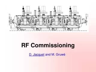
Changes at the RF system - removal of all 16 cavities and reinstallation of 12 cavities - assembly of new klystron modulators (HV power supplies instead of tubes) - removal of all old electronic and cables and replace by new technique (ELWIS) - reconstruction of the waveguide distribution system - development, test, assembly and commissioning of new control-, regulation- and diagnostictechnique - new high voltage power supply - commissioning of both 500 MHz systems • design and construction of feedback-cavities • assembly and commissioning of the feedback-system 2007-07-02 2008-09-27 Stefan Wilke, DESY MHF-e
changes by time hall SL 2007-07-02 2007-09-13 2008-09-27 tunnel SL 2007-07-02 2007-11-16 2008-09-27 Stefan Wilke, DESY MHF-e
transmitter power supply new crowbar outdoor equipment hall SL • data of 1 system: 80kV / 38A • work largely done • system tested as possible yet • tested with klystrons at 60kV / 20A klystrons Stefan Wilke, DESY MHF-e
. RF-system of PETRA III prototype Transmitter Hall PETRA-SR Transmitter Hall PETRA-SL Phase- Shifter Waveguide-Shutter 800 kW Klystron 800 kW Klystron 800 kW Klystron 800 kW Klystron Normally each transmitter drives its own 6 cavities. Option to run one transmitter on all 12 cavities. 400 kW Load 400 kW Load MT MT 400 kW Load 400 kW Load 4-Port Circulator 4-Port Circulator 100 kW Load 100 kW Load 100 kW Load 100 kW Load 3 dB Hybr. Coupler 3 dB Hybr. Coupler WG-Shutter WG-Shutter WG-Shutter WG-Shutter Phase-Shifter Phase-Shifter Phase-Shifter Phase-Shifter 3 dB Hybr. Coupler 3 dB Hybr. Coupler Interconnection Line Waveguide Power Distribution Waveguide Power Distribution PETRA Tunnel 7-cell cavities 7-cell cavities Stefan Wilke, DESY MHF-e
Waveguide Power Distribution from transmitter SL 3,0 4,8 6,0 7,0 7,8 to SR Interconnection Line Stefan Wilke, DESY MHF-e
Feedback Kicker-Cavity 14 336 10 10 1315 MHz 60 6 1435 MHz - Modified DAΦNE / PSI design - 8 ports - tuneable: 1315 – 1435 MHz - bandwidth: 140 MHz - R/Q: 73 Ω - quality factor (unloaded): 230 - 8 pieces made at DESY Stefan Wilke, DESY MHF-e
Feedback Kicker-Cavity Stefan Wilke, DESY MHF-e
Feedback Kicker-Cavity Stefan Wilke, DESY MHF-e
next steps • tunnel closed: 27st oct. (for magnet power supply tests) • testing the software system • commisioning of llrf system • interlock tests • conditioning of the cavities • high power tests • adjustment of waveguide system at high power • 2009: feedback adjustment with beam • beam for users Stefan Wilke, DESY MHF-e
The MHF-e team thank you 2007-04-25 Stefan Wilke, DESY MHF-e