Download
1 / 21
210 likes | 221 Views
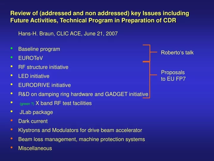
Review of (addressed and non addressed) key Issues including Future Activities, Technical Program in Preparation of CDR Hans-H. Braun, CLIC ACE, June 21, 2007 Baseline program EUROTeV RF structure initiative LED initiative EURODRIVE initiative

E N D
Review of (addressed and non addressed) key Issues including • Future Activities, Technical Program in Preparation of CDR • Hans-H. Braun, CLIC ACE, June 21, 2007 • Baseline program • EUROTeV • RF structure initiative • LED initiative • EURODRIVE initiative • R&D on damping ring hardware and GADGET initiative • (green ?) X band RF test facilities • JLab package • Dark current • Klystrons and Modulators for drive beam accelerator • Beam loss management, machine protection systems • Miscellaneous Roberto‘s talk Proposals to EU FP7
Baseline program until CDR • RF Structure development (talks of Walter and Steffen) • CTF3 (talks of Günther and Frank) • Civil Engineering and tech. infrastructure studies • Cost Study • Two Beam module design • Active pre-alignment systems • Beam physics (Daniel‘s talk) • Dynamic effects during alignment • Luminosity tuning monitor • Ring to ML & BDS alignment • Integrated feedbacks • Fast beam ion instability (DR+LET) • Intra beam scattering (DR) EU EUROTeV • Electron cloud (DR+LET) • Impedances (DR+LET) • DR lattice optimisation, tolerances, correction algorithms • BDS optimisation and participation in ATF2 commissioning • Return line design • MPS concept
FP6 EUROTeV funded activities (ongoing) Diagnostic hardware Main linac BPM‘s (100nm resolution, 10mm precision) Wide band wall current monitors bandwidth >20 GHz for drive beam diagnositcs Precision phase measurements with better 0.1 deg. Development of 3D electron cloud code (completed, shows that we have an issue in e+ ring) Beam dynamics activities
LED (=Luminosity Ensuring Design) proposal for EU FP7 • CLIC main linac module with one quadrupole including • Vibration damping for quadrupole • Active pre-alignment system with sensors • Structure BPM • Test with beam in CTF3 TBTS (beam height problem) • Vibration sensors for final doublet quadrupoles • Test of CLIC crab cavity prototypes with beam in CTF3 main beam Drive beam
EURODRIVE proposal for FP7 • Start to end simulation of drive beam includingTrajectory and optics measurement and correction algorithm • Integrate this program package in CTF3 controls and test with real beam • Beam phase measurement in CTF3
S.C. wiggler magnet development for CLIC DR Existing CERN-BINP collaboration has produced paper design including SR absorbers. Presently a short prototype is constructed for demonstration of magnetic feasibility and field measurement as input for beam dynamic simulations. ANKA wiggler team has made a paper design for a s.c. wiggler with more aggressive parameters. GADGET= (Generation And Diagnostics Gear for tiny EmiTtance)proposal for EU FP7 Design & production of full size (2m) prototype of each wiggler type including tests with beam in ANKA 2.5 GeV SR source for. Development of kickers with nominal CLIC DR parameters using solid state pulser technology Theoretical and experimental studies of IBS in regime relevant for CLIC DR at ANKA and SLS Development of diagnostic equipment and related test beamline ITB in CTF3
BINP PM wiggler BINP SC wiggler ANKA SC wiggler Contour plot of horizontal emittance with IBS as function of wiggler parameters Sketches of BINP wiggler Low vertical beta-optics in the long straight sections of ANKA: βx =14 m, βy = 1.9 m, εx = 40 nm
1.85m F D F D D D D D D D D D D F F F F F F F D D F F F D D 16.6 m 16 m 2.5m 1.4 m 22.4 m D F 8 m F F F F F F F F D D D D D D D D 1 LIL-ACS LIL-ACS LIL-ACS 1.4m 3.0m 3.0m 23.2 m DUMP 6 m 42.5 m Layout of CLEX-A (A=Accelerator housing) floor space DUMP D F TBL TL2’ DUMP TBTS DUMP 1.4m 0.75 CALIFES probe beam injector ITB DUMP walk around zone ITB = Instrumentation Test Beam Use of CALIFES beam for instrumentation R&D (for example cold BPM’s for wiggler, bunch length measurement, …)
Stand alone X band power source will allow structure testing at CERN independend of CTF3 running from 2009 on Modulator phase modulation test slot Klystron50 MW 1500 ns 50 Hz 200 MW, 0 ... 100 ns hybrid or 100 MW, 0 ... 350 ns pulse compression
DUMP TBL F F D D DUMP F F D D F F D D F F F D D D F F F F D D D D F F F F D D D D F F F F D D D D F F F F D D D F F F F D D D D F F F F D D D D F F F F D D D D F F F F D D D D D D F F 30 GHz Teststand DUMP D D D D F F D D D D F F D D DUMP D D D F F F D D D D D D D LIL LIL LIL - - - ACS ACS ACS F F D D D D F F F F F F F F D D D D D D D D LIL LIL LIL - - - ACS ACS ACS F F D D D F F F D D D DUMP DUMP Probe beam injector F 1m wide passage all around Location of X-band stand alone source (2nd floor) CTF3 X 2 Delay Loop 3.5 A - 1.4 ms 150 MeV Drive Beam Accelerator Drive Beam Injector 16 structures - 3 GHz - 7 MV/m X 5 Combiner Ring Two-beam Test Area 150 MV/m 30 GHz F F D D F ITB DUMP D D F F D D 30 GHz andPhoto injector test area Possible locations of structures powered by stand alone RF source
JLab package • Help in CTF3 commissioning • Design & performance evaluation of isochronous beamlines from ground level to deep tunnel • R&D on non-destructive transverse profile diagnostics • Design of polarized CLIC e- source. • Main beam spin transport • Decelerator beam dump design (52 needed in total)
397 klystrons 33 MW, 140 ms combiner rings Circumferences delay loop 90 m CR1 180 m CR2 540 m drive beam accelerator 2.4 GeV, 1.33 GHz CR1 1 km delay loop CR2 decelerator, 26 sectors of 810 m BDS BC2 IP1 main linac TA 9 GeV, mainbeam return line Paverage Beamline high score 80 MW 3.1 MW 0.9 MW 15 MW DBR MBR
Assuming that we can accept distributed drive beam loss equivalent to 100 W/min drive beam return line (already pretty unpleasant for activation) • Length return line 21 km, Pbeam =80MW • total loss < 2.5%, loss per km < 0.13% The issue of drive beam loss control is known for long timeTherefore we had foreseen in CTF3 • Identical wall current monitors end of injector and before each beam dump together with fast interlock for immediate gun interlock in case of differential losses • A system of beam loss monitors to detect losses smaller than wall current monitor differential resolution • A kicker to dump beam loading transients in controlled manner • Special OTR imaging devices to measure halo density distribution • But all this activities are dormant, because CTF3 with 4 kW maximum beam power doesn‘t need such sophisticated MPS and it is practically impossible to motivate these activities while other key commissioning milestones have not been reached.
Revolution time Number of Number part. stored energy instanteneous Accelerator Energy or pulse duration Bunches / Bunch / beam or pulse beam power m GeV 107 MJ GW s LHC 7000 88.9 2808 11500 362.1 4075 P HERA 920 21.1 180 7000 1.9 88 TEVATRON 980 20.9 36 24000 1.4 65 SR source 2.5 1.0 500 624 0.0012 1.2 (typical) CLIC drive beam 2.4 139.0 92664 4869 1.71 12 DB return line CLIC drive beam 2.4 0.3 3564 4869 0.07 222 decelerator injection CLIC main beam 9.0 0.2 311 400 0.002 9 main linac injection CLIC main beam 1500.0 0.2 311 400 0.30 1431 main linac injection Is it fair to compare CLIC drive beam with storage rings ? No existing single pass accelerator has pulse energy getting anywhere close MPS for drive beam needs serious studies !
Why bother about dark current, overfocusing of main beam quadrupoles will clean off d.c. electrons ! But at high energy end of linac quadrupoles are spaced by 10 modules, or 80 accelerating structures.
Some more issues which deserve more attention • Beam diagnostics - Emittance monitoring main beam and drive beam - FFS and spend beam line instrumentation - Beam-loss instrumentation • Collimator design main beam and drive beam • FF quadrupoles and supports • Control system concepts capable to deal with feedback needs • Start-up scenarios (how to switch on a 80 MW beam)related problem: tune up dumps • Impedances others than RF structures and BDS collimators (main & drive beam) • Transient RF loading in DR • Pre Damping RIng • Positron source • ...
For CDR need to get credible concepts for all components. • We try to fill holes in the study and find the required ressources • inside and out side CERN. • But what should/could be done to get confidence • In DR feasibility without building a full scale prototype • In DB decelerator feasibility without building a full sector • In low emittance transport without building a 100 GeV linac