Download
1 / 29
310 likes | 746 Views
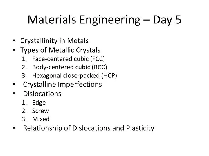
Materials Engineering – Day 5. Crystallinity in Metals Types of Metallic Crystals Face-centered cubic (FCC) Body-centered cubic (BCC) Hexagonal close-packed (HCP) Crystalline Imperfections Dislocations Edge Screw Mixed Relationship of Dislocations and Plasticity.

E N D
Materials Engineering – Day 5 • Crystallinity in Metals • Types of Metallic Crystals • Face-centered cubic (FCC) • Body-centered cubic (BCC) • Hexagonal close-packed (HCP) • Crystalline Imperfections • Dislocations • Edge • Screw • Mixed • Relationship of Dislocations and Plasticity
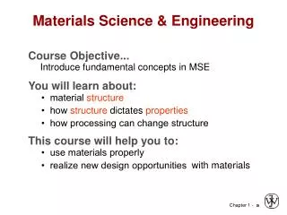
You need to know/be able to • Describe the difference between amorphous and crystalline and state how that structure affects properties. • Name the three most common types of unit cells for metals and explain how the unit cell affects properties • State the relationship of dislocation motion and planar slip on the behavior of metals, and explain how it affects strength and ductility.
Amorphous • No repeating structure (amorphous is pile of bricks compared to a brick wall (crystalline)) • Must cool very rapidly from the liquid to prevent diffusion or combine a number of incompatible (size,crystal structure, electronegativity) atoms. • Currently marketed by Liquidmetalhttp://www.liquidmetal.com/index/ in bulk and Metglashttp://www.metglas.com/products in ribbon, but still a niche market.
Crystallinity in Metals • First discovered, using x-ray diffraction, in the early years of the 1900’s. • The crystallinity of metals is simple. Why? Strong, non-directional, metallic bonding. (We are not dealing with positive and negative ions of different size.) We are dealing with spheres of about the same size. • It involves several concepts. Here are two of them. • The close-packed plane. • The unit cell.
Section 3.4 – Metallic Crystal Structures • How can we stack metal atoms to minimize empty space? 2-dimensions vs. Now stack these 2-D layers to make 3-D structures
Metallic Crystal Structures • Tend to be densely packed. • Reasons for dense packing: - Typically, only one element is present, so all atomic radii are the same. - Metallic bonding is not directional. - Nearest neighbor distances tend to be small in order to lower bond energy. - Electron cloud shields cores from each other • Have the simplest crystal structures. We will examine three such structures...
Body Centered Cubic Structure (BCC) • Atoms touch each other along cube diagonals. --Note: All atoms are identical; the center atom is shaded differently only for ease of viewing. ex: Cr, W, Fe (), Tantalum, Molybdenum • Coordination # = 8 Adapted from Fig. 3.2, Callister 7e. 2 atoms/unit cell: 1 center + 8 corners x 1/8 (Courtesy P.M. Anderson)
Atomic Packing Factor: BCC a 3 a 2 Close-packed directions: R 3 a length = 4R = a atoms volume 4 3 p ( 3 a/4 ) 2 unit cell atom 3 APF = volume 3 a unit cell • APF for a body-centered cubic structure = 0.68 a Adapted from Fig. 3.2(a), Callister 7e.
Face Centered Cubic Structure (FCC) • Atoms touch each other along face diagonals. --Note: All atoms are identical; the face-centered atoms are shaded differently only for ease of viewing. ex: Al, Cu, Au, Pb, Ni, Pt, Ag • Coordination # = 12 Adapted from Fig. 3.1, Callister 7e. 4 atoms/unit cell: 6 face x 1/2 + 8 corners x 1/8 (Courtesy P.M. Anderson)
Atomic Packing Factor: FCC Close-packed directions: 2 a length = 4R = 2 a Unit cell contains: 6 x1/2 + 8 x1/8 = 4 atoms/unit cell a atoms volume 4 3 p ( 2 a/4 ) 4 unit cell atom 3 APF = volume 3 a unit cell • APF for a face-centered cubic structure = 0.74 maximum achievable APF Adapted from Fig. 3.1(a), Callister 7e.
B B B B C C C A A A B B B B B B B A sites C C C C C C B B sites sites B B B B C sites A B C FCC Stacking Sequence • ABCABC... Stacking Sequence • 2D Projection • FCC Unit Cell
Hexagonal Close-Packed Structure (HCP) A sites Top layer c Middle layer B sites A sites Bottom layer a • ABAB... Stacking Sequence • 3D Projection • 2D Projection Adapted from Fig. 3.3(a), Callister 7e. 6 atoms/unit cell • Coordination # = 12 ex: Cd, Mg, Ti, Zn • APF = 0.74 • c/a = 1.633
nA VCNA Mass of Atoms in Unit Cell Total Volume of Unit Cell = Theoretical Density, r Density = = where n = number of atoms/unit cell A =atomic weight VC = Volume of unit cell = a3 for cubic NA = Avogadro’s number = 6.023 x 10²³ atoms/mol
R a 2 52.00 atoms g = unit cell mol atoms 3 a 6.023x10²³ mol volume unit cell Theoretical Density, r • Ex: Cr (BCC) A =52.00 g/mol R = 0.125 nm n = 2 a = 4R/ 3 = 0.2887 nm theoretical = 7.18 g/cm3 ractual = 7.19 g/cm3
Grand Truth - Strengthening in metals • Yield strength is the onset of plastic flow • Plastic flow results from planar slip • Planar slip results from dislocation motion • Therefore • To increase Strength - Prevent/Impede Dislocation Motion • Ductility Corollary • Impeding dislocation motion makes slip harder • Lower slip means lower ductility • Therefore: • Increasing Strength generally Lowers Ductility
Concept of Slip • Slip in metal crystals is the primary mechanism of plastic deformation. • Adjacent planes of atoms slip, or move past one another. This deformation is not recoverable. Atoms have new neighbors. It is plastic deformation. • A slip system consists of the most close-packed planes in the crystal and the most close-packed directions in that plane. • Crystallographers have studied the geometry of the crystals and here is the ranking.
Slip Systems and Ductility The basic ductility is going to be tied to the type of crystallinity. But, ductility rises and falls within a material type due to the way the material is processesed. This is a very important lesson!
nuclei grain structure crystals growing liquid Imperfections in Solids • Solidification- result of casting of molten material • 2 steps • Nuclei form • Nuclei grow to form crystals – grain structure • Start with a molten material – all liquid Adapted from Fig.4.14 (b), Callister 7e. • Crystals grow until they meet each other
Imperfections in Crystals • Point imperfections • Vacancy. Lattice point not occupied by an atom. Position of nearby atoms slightly affected. • Impurity atom – substitutional. An atom of approximately the same size can, and will, be found filling a lattice point. Position of nearby atoms is affected. Eg. Chromium in Iron as in stainless steel. • Impurity atom – interstitial. A much smaller atom is dissolved in the unoccupied space in the lattice. Eg. Carbon in iron as in steel.
Point Defects Vacancy distortion of planes self- interstitial distortion of planes • Vacancies: -vacant atomic sites in a structure. • Self-Interstitials: -"extra" atoms positioned between atomic sites.
Point Defects in Alloys Two outcomes if impurity (B) added to host (A): • Solid solution of B in A (i.e., random dist. of point defects) OR Substitutional solid soln. (e.g., Cu in Ni) Interstitial solid soln. (e.g., C in Fe) • Solid solution of B in A plus particles of a new phase (usually for a larger amount of B) Second phase particle --different composition --often different structure.
Area Imperfections • The most common area imperfections are grain boundaries. (The grains adhere tightly.) photomicrograph
Imperfections in Solids Edge Dislocation Fig. 4.3, Callister 7e.
Imperfections in Solids Screw Dislocation Screw Dislocation b Dislocation line (b) Burgers vector b (a) Adapted from Fig. 4.4, Callister 7e.
Slip and Dislocation Motion • It is possible to predict yield strength in perfect crystals. The value is G/5. This would imply yield in iron over 1,000,000 psi. Way too high! The idea that all slip system atoms simultaneously move in plastic deformation is not correct. • Instead, if you look at a dislocation moving through and producing one unit of slip by it’s motion, the value is about G/180. This agrees with experiment. • Slip occurs locally by dislocation movement.
Dislocation Motion • Schematic, and picture of slip in a crystal. Slip paralled to direction dislocation moves. Dislocations Bubble raft movie
More on Dislocations – The screw dislocation. • Various concepts Slip produced by a screw dislocaton Notice that slip is perpendicular to the direction the dislocation moves.
Imperfections in Solids Dislocations are visible in electron micrographs Adapted from Fig. 4.6, Callister 7e.